
plc circuit diagram
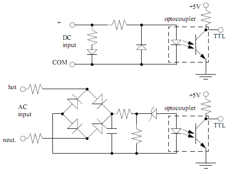
The operation of PLC input and output cards is critical for ensuring reliable communication between the PLC and external devices. Input cards are designed to interface with sensors and input devices, receiving signals that may vary in voltage levels. The need for an external power supply arises because the input card itself does not generate the necessary voltage to power these devices. The ladder logic diagram serves as a visual representation of the connections and logic flow, facilitating easier understanding and troubleshooting during installation and maintenance.
In the input circuitry, the use of optocouplers plays a pivotal role. These components allow for the safe transfer of signals between different voltage domains while preventing high voltages from affecting the PLC's internal components. The design typically includes resistors to limit current and ensure that the optocoupler operates within its specified range. Additionally, protection diodes may be included to prevent damage from reverse polarity, ensuring that the circuit remains functional even in adverse conditions.
Output modules operate similarly, acting as interfaces between the PLC and external loads, such as motors or lights. These modules require an external power source to energize the connected devices. The conversion from the 5VDC logic level to higher voltage levels is achieved through the use of optocouplers or relays, which can handle the higher currents and voltages needed for the external circuits. The isolation provided by these components protects the PLC from potential damage caused by surges or faults in the external circuitry.
Overall, the integration of input and output cards within a PLC system is essential for creating a robust and flexible control environment. Proper circuit design, including the use of optocouplers and protective components, ensures that the system can operate safely and effectively across a variety of applications.PLC input cards rarely supply power, it means that needs external power supply for the inputs and sensors. Below is an Input card and Ladder Logic diagram that shows how to connect an AC input card. The PLC inputs must convert a variety of logic levels tothe 5VDC logic level used on the data bus. This can be done with circuits similar as the picture below. Basically the circuits condition the input to drive an optocoupler. This electrically isolates the external electrical circuitry from the internal circuitry. Other circuit components are used to guard against excess or reversed voltage polarity. As with the input modules, output modules rarely supply any power, but instead act as switch. External power supplies are connected to the output card and it will switch the power on or off for each output. PLC outputs must convert the 5VDC logic level on the PLC data bus to external voltage levels. The circuits will show on the picture below. Basically the circuits use an optocoupler to switch external circuitry. This electrically isolates the external electrical circuitry from the internal circuitry. Other circuit components are used to guard against excess or reversed voltage polarity. 🔗 External reference
Related Circuits
The circuit comprises an N-MOSFET voltage follower (T1, common drain) and a current source (T2, NPN Darlington). The current source is set to 2.2 Amps. With a supply voltage of 40V, the circuit can deliver approximately 17W into an...
There are two regulator circuits that utilize the L200 integrated circuit from SGS-Thomson to regulate voltage and current. In circuit Fig. 1, the output voltage can be adjusted using the variable resistor RV1. In Fig. 2, both output voltage...
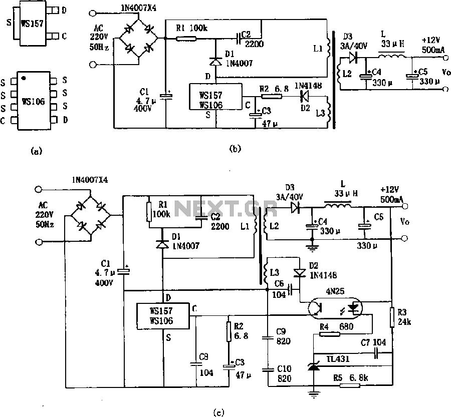
The WS157 or WS106 is a low-power miniature switching power supply that has been developed in recent years. It functions as a regulated switching power supply control device, featuring integrated internal control circuitry and power switches on a single...
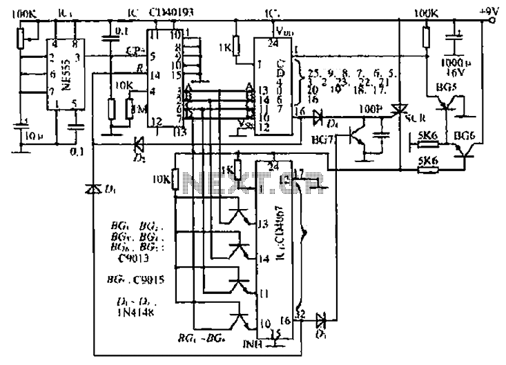
The circuit consists of an oscillator, a counter, and an Iseki circuit divided into three parts. The oscillator is based on the NE555 timer and several external RC components, generating a pulse signal for the counter. The instantaneous power...
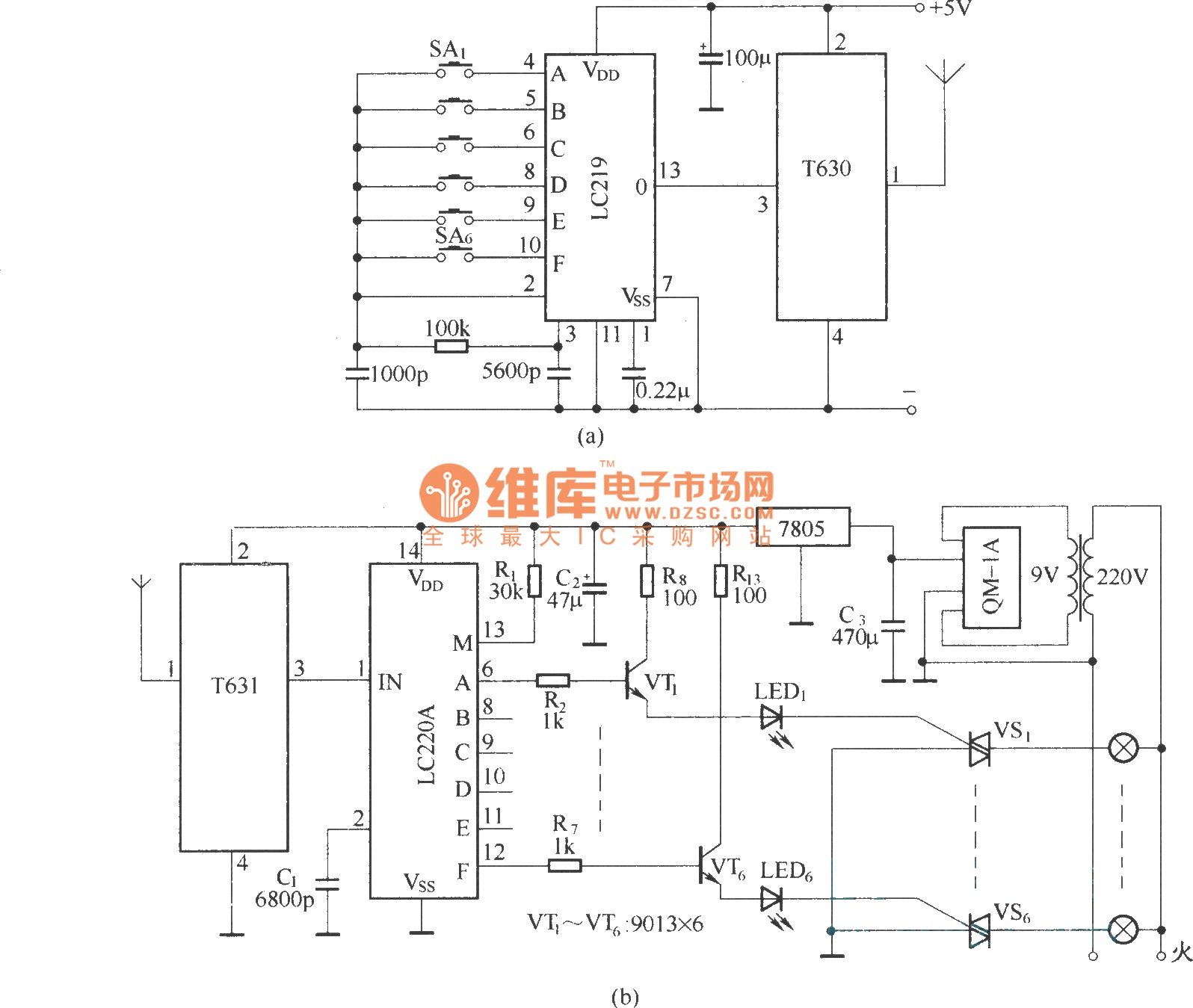
The circuit utilizes the long-wave wireless transceiver T630/T631 to manage a 6-channel load. It is characterized by low power consumption, high resistance to interference, and a simple structure. The circuit design incorporates the T630/T631 transceiver, which operates in the long-wave...
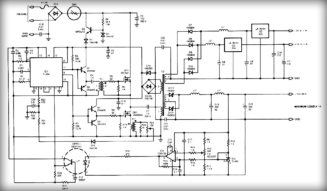
This power supply employs two VN400A 400-Volt MOSFETs arranged in a half-bridge configuration. The outputs provide +5V at 20A and +15V at 1A. Low-current outputs utilize three-terminal regulators, allowing for either 12 Volts or 15 Volts to be achieved...
Warning: include(partials/cookie-banner.php): Failed to open stream: Permission denied in /var/www/html/nextgr/view-circuit.php on line 713
Warning: include(): Failed opening 'partials/cookie-banner.php' for inclusion (include_path='.:/usr/share/php') in /var/www/html/nextgr/view-circuit.php on line 713