
A thirty light water digital control circuit
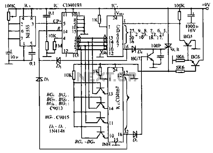
The described circuit integrates several components to achieve a precise counting and control mechanism. The NE555 timer serves as the core oscillator, generating clock pulses that drive the counter. The external RC elements are crucial for defining the timing characteristics of the oscillator, which directly influences the pulse frequency sent to the counter.
The counter utilizes a BCD output format, allowing for straightforward digital representation of the counted pulses. The use of the CD4067 analog switches enables efficient control of the signals based on the counter's state, allowing for selective activation of subsequent stages in the circuit.
Transistors BG1 to BG4 serve as protective elements, ensuring that the circuit operates within safe limits by blocking unwanted signals when necessary. The interaction between the components is carefully designed to manage power consumption effectively, particularly in the case of the thyristor IC4, which is only activated under specific conditions to minimize power draw.
The circuit's operational cycle is designed to repeat continuously, allowing for dynamic control over the connected lamp system. The inclusion of a potentiometer for flow rate adjustment provides flexibility in operation, making this circuit suitable for various applications requiring precise timing and control. Overall, the circuit exemplifies a well-thought-out design that balances functionality, efficiency, and ease of use. By the oscillator circuit, a counter, Iseki circuit of three parts. Oscillation circuit by the time base manifold NE555 and several external RC element. Its function is to prov ide a pulse signal to the counter. Instantaneous power between, since derivative action C], Rl, and the counter is cleared. With ICl IC2 delivery continued to pulse count after counting the number of pulses output is put in the form of four-digit BCD code. In the ABCD output of the counter, in parallel with IC3, IC4 two single six-speed analog switch IC CD4067.
In the counter counts to 15 before the pulse, only IC3 internal analog switch is turned on. Since the power supply circuit IC4 thyristor not conducting derived less power, and therefore although the input terminal 1C, connected in parallel, but internal analog switches non-conductive. Transistor BGi ~ BG4 before IC4 not be turned off by applying a voltage to block IC2 output signal is applied to IC4, IC4 protect the role.
When IC2 count to 15 pulses when, IC, analog switch block 16 is turned on, that is, it goes 16 feet high. On the one hand, by the IC2 R end in Makati and is cleared; the other, through D3 female hair thyristor, IC4 energized, thus starting from the first 16 pulses, IC4 of the analog switch off will gradually lead through.
Meanwhile, BG6 conduction, BG, reverse bias is turned off. IC, the INH (inhibit) terminal from low to high, the internal switch off the whole, 8421 yards invalid input. That is, since the beginning of the 16th pulse, count the number of functions performed by the IC3 jurisdiction Ic4.
When the pulse count to the first 32 Al, 16 block IC4 switch is turned on, 16-pin goes high, by Dl added IC2 ©R end and is cleared. At the same time, but also through D4 added Bq on the base, making it saturated conduction, SCR trigger terminal is shorted to ground off, IC4 lose power, BG6 off, BG5 conduction, IC INH terminal 3 is changed back to low, enter their valid BCD code, circuit and back to working state when power is applied.
Again and again the cycle continues, they will have control thirty recirculating lamp system voltage, the flow rate by adjusting potentiometer.
Related Circuits
For several years, a rear fog lamp has been mandatory for trailers and caravans to improve visibility in foggy conditions. When this fog lamp is activated, the fog lamp of the towing vehicle must be turned off to prevent...
This circuit is a basic design for flashing one or more LEDs, as well as for alternately flashing multiple LEDs. It employs a 555 timer configured as an astable multivibrator, allowing for variable frequency operation. When the preset is...
The motor switch control circuit depicted in the figure provides two speed settings for counter-steering, allowing for operation at two speeds in opposite directions. The motor switch control circuit is designed to facilitate the operation of a motor at two...
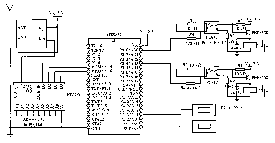
This design aims to create a long-distance wireless remote control switch lighting control system, which consists of a transmission system and a reception system. The system utilizes wireless transceiver modules for RF transmission and reception. The transmitting portion mainly...
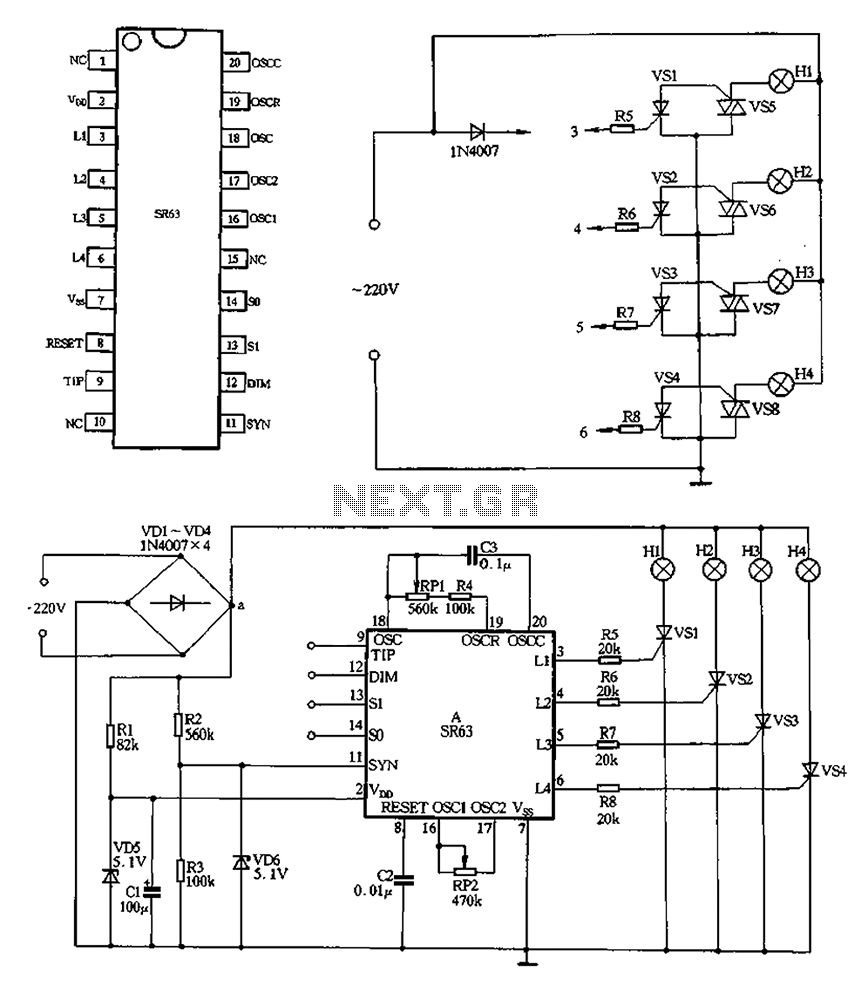
220V AC is converted to DC after passing through a VDI ~ VD4 bridge rectifier. The output from one point supplies power directly to lights H1 through H4. Another route passes through R1, a buck converter, and VD5, which...
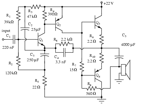
Note that Q3 and Q4 in the figure below are complementary, with Q3 being an NPN transistor and Q4 being a PNP transistor. This circuit is suitable for moderate power audio amplifiers. For a detailed explanation of this circuit,...