
Suspended Bicore circuit for robots
The bicore circuit is a fundamental component in the BEAM robotics platform, primarily functioning as an oscillator. The core functionality is derived from its ability to produce alternating signals that can be used to control various robotic functions. The outputs of the bicore oscillate in a specific pattern, which can be described as (+ -, - +, + -, - +). This behavior allows the circuit to drive motors or control LED indicators, depending on the application.
Central to the operation of the bicore is the resistor R1, which dictates the frequency of the oscillations. The choice of resistor value significantly influences the performance characteristics of the circuit. For rapid oscillations, a lower resistor value is preferred, while a higher value results in slower oscillations. It is common practice to select resistor values within the range of 100K to 10M, with 1.6M being a frequently utilized value.
The circuit also incorporates a capacitor, typically a 0.22uF capacitor, which works in conjunction with R1 to stabilize the oscillation frequency and shape the waveform output. The integration of a 74AC240 buffer/driver IC enhances the circuit's capability, allowing for greater control over the output signals and facilitating the driving of larger loads, such as motors.
In practical applications, the bicore can be utilized in a variety of configurations. For instance, in photovores, the oscillating output can be used to control motors that steer toward light sources. Similarly, in robotic walkers, multiple bicore circuits can be combined to coordinate the movement of several motors, enabling complex locomotion patterns. The versatility of the bicore circuit makes it an essential building block for intermediate to advanced BEAM robotics, where multiple units can be interconnected to create sophisticated robotic systems capable of performing a wide range of tasks.The bicore is the basis of advanced BEAM! Most intermediate to advanced BEAM robots are built off of the bicore. Uses go all the way from photovores to servo motor drivers to walkers to.... You get the idea. What it is is basically just an oscillator who's outputs go (+ - , - +, + -, - +....) and the rate of oscillations is controlled by the resister (R1). Another cool thing is that they can be grouped together to form large complex structures. Really a very cool circuit once you figure out how it works. R1 R1 controls the rate of oscillation. If you want quick oscillations you use a low value resister, long oscillations you use large value resister.
I normally don't use values below 100K or over 10M, 1.6M is a common value. As I noted above it has a very wide range of uses. Photovores, light seeking heads, walkers, servo motor drivers.... Just to name a few. The walker category is HUGE!! There's walkers with 2 motors to 12 motors. No sensors to electronic compasses and sonar. A single bicore can't do much other than blink a couple LEDs or make a motor go back (which is sometimes what you might want) but they are most useful in groups. R1 (see circuit notes) 1 Digikey See circuit notes .22uF Capacitor 2 Digikey P4966-ND 74AC240 1 Digikey 74AC240PC-ND
🔗 External reference
Related Circuits

This circuit provides protection for telephones, EPABX systems, telephone modems, and similar devices against lightning discharges and line voltage spikes. It incorporates a safety capacitor and gas discharge components. The circuit employs a safety capacitor to filter out high-frequency noise...
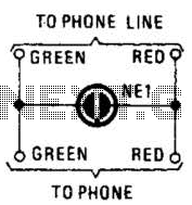
A neon lamp can easily be added to the phone line to act as a ring indicator. It is perfect for times when you cannot hear the phone. The integration of a neon lamp as a ring indicator in a...

Recently, the Overunity and Energetics online forums, which serve as significant platforms for members of the Open Source and Free Energy communities, have been discussing a remarkable phenomenon known as the Rosemary Ainslie Circuit. This circuit is named after...

The project demonstration has been successfully completed, with the only remaining task being the final project report due on June 15, which will be integrated with a conference paper. This update marks the last entry in the electronic notebook,...
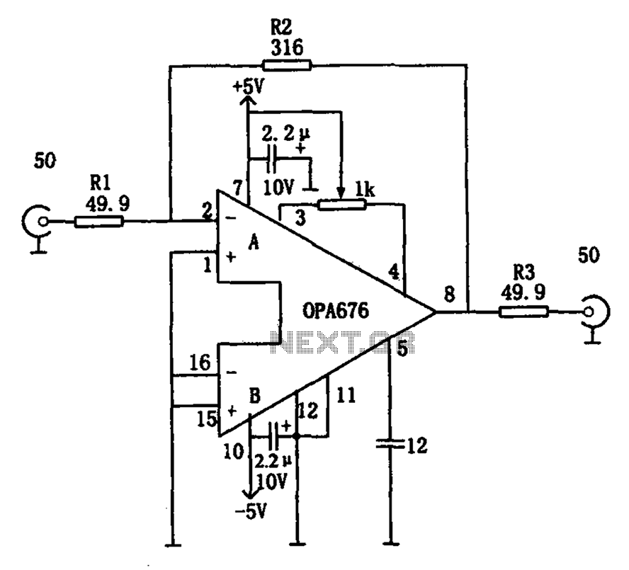
The circuit features a broadband video amplifier with a 50-ohm input/output impedance. To ensure optimal signal transmission and minimize reflected signals, it is often necessary to match the input and output impedances of the amplifier. The broadband video amplifier...
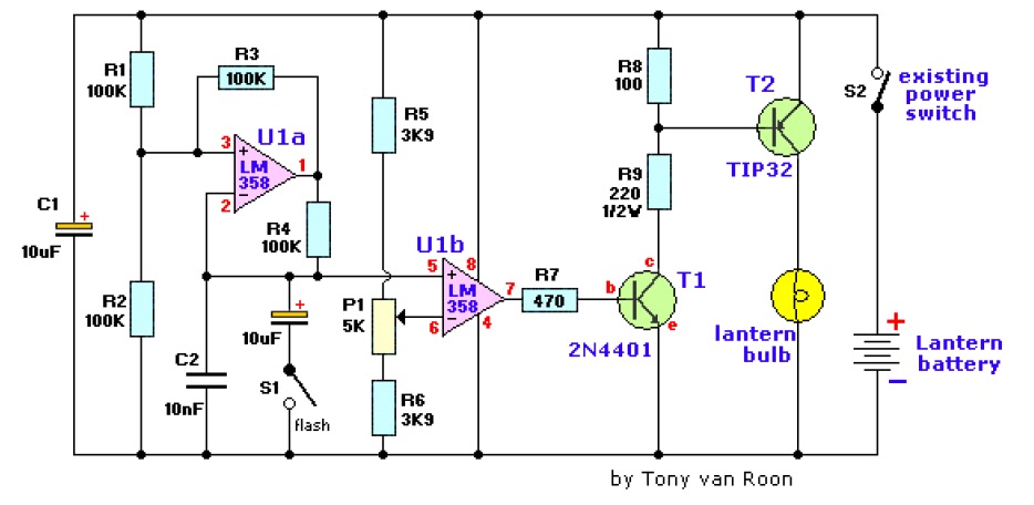
The electronic lantern control circuit enhances an existing battery-powered lantern or flashlight, or can be incorporated into a custom design, by providing high-efficiency dimming and flashing capabilities. This circuit is particularly useful in automotive applications, serving as an effective...
Warning: include(partials/cookie-banner.php): Failed to open stream: Permission denied in /var/www/html/nextgr/view-circuit.php on line 713
Warning: include(): Failed opening 'partials/cookie-banner.php' for inclusion (include_path='.:/usr/share/php') in /var/www/html/nextgr/view-circuit.php on line 713