
Politely welcoming electronic doorbell
The electronic doorbell circuit operates by utilizing a trigger control mechanism that activates the audio output when the doorbell button is pressed. The button (S) serves as the primary input, which, when engaged, completes the circuit. This action can also be influenced by magnetic switches (SA) that may be employed to enhance the circuit's functionality, allowing for additional activation methods.
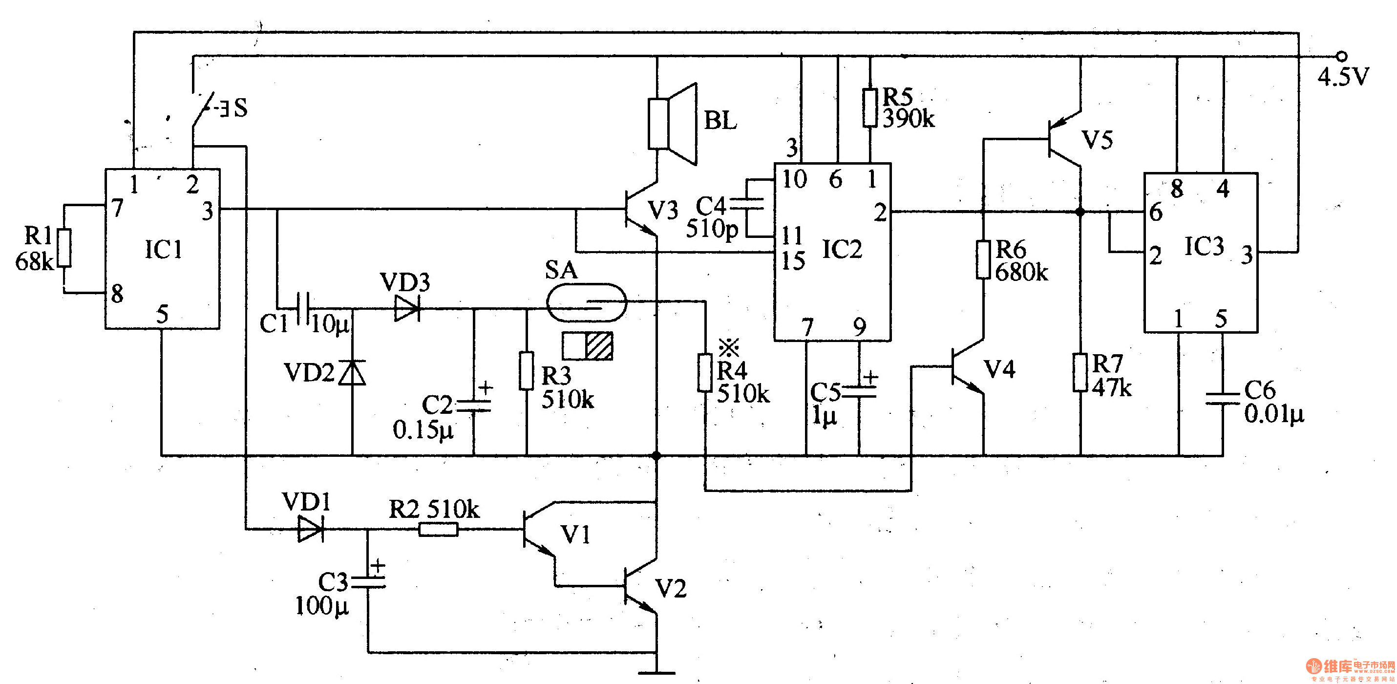
Transistors (V4 and V5) function as amplifiers and switches in the circuit, controlling the flow of current based on the input received from the doorbell button and magnetic switches. The resistors (R3, R4, and R6) are used to limit current and set appropriate voltage levels for the transistors to operate efficiently. Diodes (VD2 and VD3) are included to prevent reverse polarity and protect sensitive components from voltage spikes.
The audio amplifier output circuit is responsible for amplifying the sound generated by the music circuit, which produces the welcoming tones when the doorbell is activated. The voice delay control circuit adds a feature that allows for a brief pause before the sound is emitted, enhancing the overall user experience by providing a more refined auditory response.
This circuit design emphasizes reliability and user-friendliness, making it suitable for various residential applications. The combination of these components ensures that the electronic doorbell functions effectively, delivering a pleasant sound to greet visitors.The politely welcoming electronic doorbell circuit is composed of the trigger control circuit, audio amplifier output circuit, music circuit, voice delay control circuit, and it is shown in Figure 3-122. Trigger control circuit is composed of the doorbell button S, magnetic switches SA, transistors V4, V5, resistors R3, R4, R6, diodes VD2, VD3, and capacitor..
🔗 External reference
Related Circuits
This is an electronic siren circuit diagram. The sound produced imitates the rise and fall of an American police siren. When first switched on, the 10µF capacitors are discharged, and both transistors are off. When the push-button switch is...
It is said that mice are more sensitive to electromagnetic fields, which is why high-voltage grids generally yield poor results in rodent control. The electronic rodent control system described here does not use high-voltage power lines, thus it does...
This circuit generates a ringing sound similar to that produced by modern telephones. It comprises three nearly identical oscillators connected in a series configuration, each generating a square wave signal. The frequency of each oscillator is determined by the...
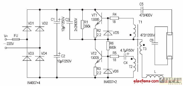
The inductive ballast has several drawbacks, including larger size and weight, high power consumption, and noise generation. In contrast, the electronic ballast features a low-voltage starter, is non-stroboscopic, operates silently, is energy-efficient, and provides immediate lighting without flickering. This...
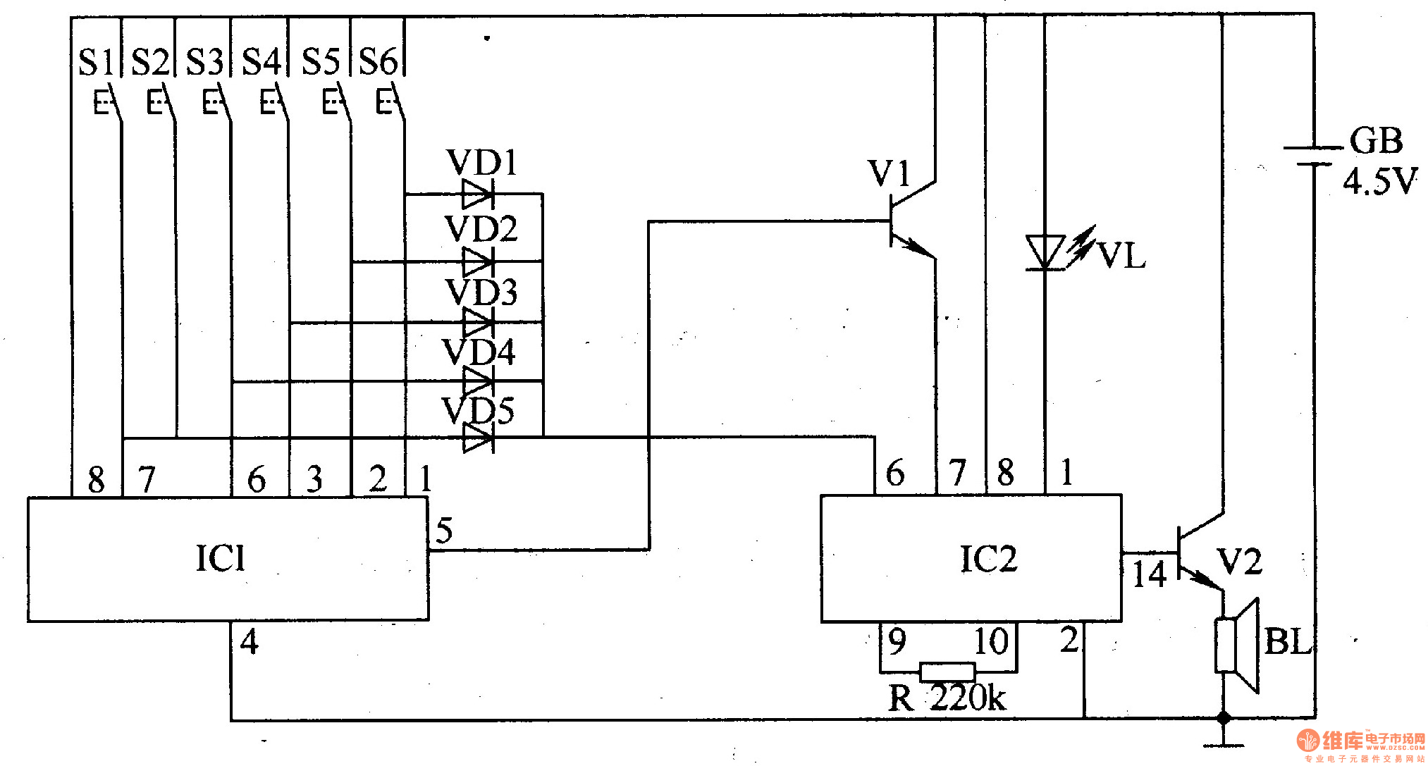
The electronic doorbell circuit utilizes a password mechanism and includes both an electronic password circuit and a music generation circuit, as illustrated in Figure 3-118. The electronic password circuit is comprised of integrated circuit IC1, keys S1-S6, and diodes...

Various types of amplifiers include power amplifiers, audio amplifiers, tube amplifiers, stereo amplifiers, sensor amplifiers, RF amplifiers, sound amplifiers, and video amplifiers. Amplifiers are critical components in electronic circuits, serving to increase the amplitude of signals. Each type of amplifier...