
20- 40W electronic ballast principle and maintenance

The components of the circuit serve specific functions: The kenotron VD1 forms the smoothing circuit with the bridge rectifier VD4, while filter capacitors C1 and C2 are connected in series. C1 receives the intersection of idle and direct current voltage of 310V, while C2, after commutation and filtering, provides 220V alternating current to power the high-frequency inverter circuit. Resistors R1 and R6 create a feedback resistance, allowing VT2 to turn on and provide biasing, thus stimulating VT1 and VT2 to form self-excited oscillation. Resistor R1 and capacitor C3 together create a parallel starting circuit that reduces losses from overvoltage. To ensure reliable operation, capacitor C3 should have a voltage rating greater than twice the mains voltage, with a rating of 630V recommended. Diodes D5 and D6 protect transistors VT1 and VT2 and are connected in parallel to reduce the charge memory effect between the base and emitter, improving the switching speed of the transistors.
The voltage transformer T provides mutual inductance coupling for the signal and consists of three windings: T1 with 3 turns, T2 with 3 turns, and T3 with 5 turns. Capacitor C4 is connected to the base and emitter of VT2 to prevent sudden changes in potential, offering protection to the transistor. Starting capacitor C5 blocks direct current voltage from reaching the fluorescent tube while allowing high-frequency alternating current of 20kHz to pass. The choke coil L and capacitor C6 form a series resonance circuit that regulates the brightness of the fluorescent tube and the working current of the modulator tube.
The primary function of the electronic ballast is to convert mains frequency power of 50Hz to high-frequency power of 20kHz to directly illuminate the fluorescent tube. The operational sequence begins with powering on, where 310V direct current, after commutation and filtering, is connected in parallel with R5 in series through C3 and R1, providing a narrow current pulse to the base of VT2, turning it on initially. When VT2 is activated, the current flows through various components, including C5, the filament of the modulator tube, C6, and the voltage transformer T3, ultimately inducing voltages that activate VT1 and VT2 in a coordinated manner. The saturation of VT1 allows the current to continue circulating through the system, maintaining the operation of the electronic ballast and ensuring stable illumination of the fluorescent tube.The shortcoming of the inductive ballast is that volume and weight are larger, one`s own power consumption is great, there are noises. The electronic ballast has low-voltage starter, non-stroboscopic, has no noise, energy-efficient, immediate advantage in the lighting twinkling of an eye, so the electronic ballast has broader development space.
Th is circuit is commutated smoothing circuit, power switch and driving circuit, ballast and filament load loop three part to make up. Make up the function of each component of the circuit as follows: The kenotron VD1 makes up the smoothing circuit of the bridge rectifier VD4, filter capacitor C1, C2 series connection, function to receive the intersection of idler and direct-current volts of 310V in C1, the intersection of C2 and both ends after commutating and filtering the intersection of 220V and alternating current, offer the working power for postern high-frequency inverter circuit.
The resistance R1, R6 arises and shakes the resistance, original for VT2 turns on and offers biasing, thus stimulate VT1, VT2 and form self-excited oscillation. Resistance R1 and electric capacity C3 make up and step down the starting circuit in parallel at the same time, can reduce the losses that over voltage brings to a certain extent.
In order to guarantee the electric capacity C3 reliable operation, its withstand voltage value should choose to be greater than the mains voltage of twice, C3 withstand voltage value is 630V. Diode D5 and D6, its function is to protect the triode VT1, VT2, connecting in parallel can weaken the memory effect of electric charge greatly between triode base electrode and emitter, thus improve the switch speed of the triode.
The voltage transformer T plays a mutual inductance coupling of signal role. It to wind by single-stranded the intersection of core wire and T1, T2, T3 at magnetic ring formative, because gas switching tube and its the intersection of driving circuit and part to contact interdependence closely, so relation between the the intersection of they and parameter in process of production relatively difficult to confirm. T1 is 3 circles, T2 is 3 circles, T3 is 5 circles in this circuit. And electric capacity C4 is connected to VT2 base electrode and emitter, can prevent the base electrode and launch the sudden change of interpolar electric potential, can protect the triode VT2 to a certain extent.
Electric capacity starting capacitance in C5, have block to circulate on the function exchanged, prevent the direct-current volts direct access fluorescent tube of 310V, allow high-frequency alternating current voltage of 20kHz to pass. Choke coil L, electric capacity C6 of syntony make up the series resonance circuit, the fluorescent tube of the brightness and modulator tube working current of the restriction that its function arises.
The basic function of the electronic ballast is to convert the mains frequency power of 50Hz to 20kHz high-frequency power, and light the fluorescent tube directly. Its working phase is: After powering on, 310V direct-current volts after commutating and filtering is connected in parallel and connected with R5 in series through C3, R1, providing a narrow current pulse for base electrode of VT2 makes VT2 turned on at first.
At time when VT2 turns on, the route is that the electric current circulates: V C5 Filament on the modulator tube C6 Lower end filament of the modulator tube Choke coil L Voltage transformer T3 Collecting electrode of VT2 emitter Ground looping-in, charge the electric capacity C6 of syntony. , to the reaction coupling of T1 and T2, the induced voltage on T1 will make the triode VT1 turned on because of the coil T3 of the voltage transformer T, and the induced voltage on T2 will make VT2 end.
At time when VT1 saturation is turned on, the route is that the electric current circulates: Electric capacity C6 of syntony Filament on the modulator tube C5 Collectin 🔗 External reference
Related Circuits
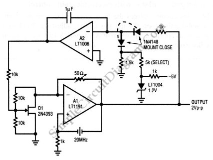
This is a quartz-stabilized oscillator circuit with electronic gain control. Replacing the common filament lamp for amplitude stabilization, this circuit uses... This circuit represents a quartz-stabilized oscillator featuring electronic gain control, which enhances the stability and precision of the output...
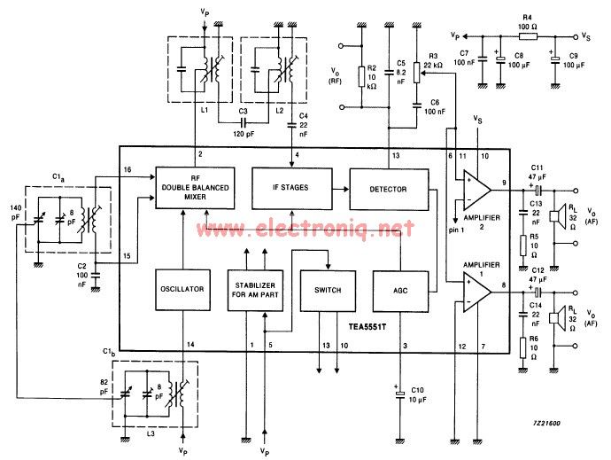
The TEA5551T monolithic integrated radio circuit can be utilized to design an AM radio receiver circuit intended for portable use with headphones. This circuit incorporates all necessary components for a complete AM radio receiver, including a fully integrated AM...
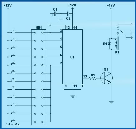
Circuit diagram schematics of electronic keys, electronic locks, digital electronic locks, transistor code locks, and combination electronic locks. The circuit schematics for electronic locking mechanisms encompass a variety of designs tailored to enhance security and convenience in access control systems....
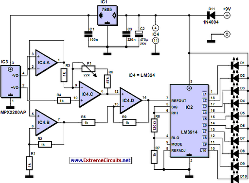
While it may lack the aesthetic appeal of traditional mercury barometers featuring elongated glass tubes mounted on intricately carved wood, the Torricelli barometer presented here serves as a functional equivalent and an electronic representation of the original Torricelli barometer....
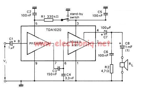
The TDA1020 is a monolithic integrated 12 W audio amplifier housed in a 9-lead single in-line (SIL) plastic package. Although it is designed primarily for car audio applications, it can also be utilized in various other audio applications. The TDA1020...
This simple and cost-effective ding-dong electronic doorbell circuit is based on IC 8021-2. The IC has an integrated circuitry that generates a ding-dong sound each time its pin 3 is pulled low. The sound is stored in the IC...