
Portable 230V lamp flasher circuit diagram

The portable 230V lamp flasher circuit is designed for versatility and efficiency, making it suitable for a variety of applications, including decorative lighting and signaling. The use of a battery power source enhances its portability, allowing it to be used in locations without access to mains power. The oscillator's design is based on a multivibrator configuration that alternates the states of the transistors, effectively controlling the on-off operation of connected loads.
The adjustable frequency feature allows users to customize the flashing speed, which can be particularly useful for different aesthetic requirements or signaling purposes. The inclusion of variable resistors PR1 and PR2 for frequency and duty cycle adjustment adds to the circuit's flexibility, enabling fine-tuning to achieve the desired visual effects.
The circuit's reliance on low-noise transistors minimizes interference and enhances performance, making it ideal for applications where sound and light quality are critical. The specified component values, including resistors and capacitors, are chosen to optimize the performance of the oscillator and ensure stable operation across various conditions.
Furthermore, the incorporation of a SCR (Silicon Controlled Rectifier) in the design allows for controlled switching of higher voltages, making the circuit capable of handling significant AC loads. This feature is particularly advantageous for applications requiring robust performance and reliability.
Overall, the circuit's design emphasizes low-cost implementation, ease of assembly, and efficient operation, making it an excellent choice for hobbyists and professionals alike seeking a reliable lamp flasher solution.Portable 230V lamp flasher circuit diagram. The circuit is completely transistorised and battery-powered. The free-running oscillator circuit is realised working with two low-power, low-noise transistors T1 and T2. One of these two transistors is constantly conducting, whilst the other is blocking. Because of normal charging and discharging of cap acitors C1 and C2, both the transistors alternate between conduction and non-conduction states. This is a portable, 230V high-power incandescent electric lamp flasher circuit diagram. It is actually basically a double flasher (alternating blinker) which could manage two different 230V AC loads (bulb lamps L1 and L2). The circuit is completely transistorised and battery-powered. The free-running oscillator circuit is realised working with two low-power, low-noise transistors T1 and.
This is the 200W lamp flasher circuit diagram. The frequency/speed of the lamp flashing can be adjust with the range of 1Hz to 5Hz. You can use the PR1 variable resistor (trimpot) to adjust the flashing speed. The duty cycle of lamp flashing can be adjusted using PR2 variable resistor. The DC input power supply. This is low cost fully transistorised inverter circuit capable of driving medium loads of the order of 40 to 60 watts using battery of 12V, 15 Ah or higher capacity. Transistors T1 and T2 (BC548) form a 50Hz multivibrator. For obtaining correct frequency, the values of resistors R3 and R4 may have to be changed. This is a 220V LED flasher circuit which is intended as a reliable replacement to thermally-activated switches used for Christmas tree lamp-flashing.
This a cheap circuit and easy to build. Schematic diagram: Component Parts: R1_ 100K R2, R5_ 1K R3, R6_ 470R R4_ 12K C1_ 1000 µF 25V D1-D4_ 1N4007 D5_ SCR P0102D Q1_ BC327 Q2_ BC337 SK1_. The following is LED Flasher circuit which use 2 transistors for LED switching. The circuit works similar to flip-flop operation. Component Parts List: R1 = 10M ohm R2 = 1K - 100K ohm R3 = 470 ohm C1 = 0. 47 F - 10 F/25V D1 = 1N914 Q1 = 2N3904 Q2 = 2N3906 Led = High Brightness. This circuit consume low current supply (about 2mA), so will have a long battery life for supplying the circuit.
The circuit built based on a low noise, high gain two stage PNP and NPN transistor amplifier, using DC negative feedback through R6 to stabilize the working conditions quite precisely. 🔗 External reference
Related Circuits

The triangular wave circuit consists of two operational amplifiers (OPs). R62 serves as the offset adjustment, while R27 is utilized for peak adjustment. A switch is included to select different resistances, allowing for the generation of triangular waves at...

This document describes a specific module utilizing the CF8865 switching power supply circuit, which employs the integrated control module CF8865. In the figure, transistors VT4 and VTs are controlled by the excitation transformer Tz. The output is processed through...

Most of the PC desk lamps available in the market illuminate whenever there is input power. These do not consider whether there is an actual need for light. The typical design of PC desk lamps operates on a straightforward principle:...
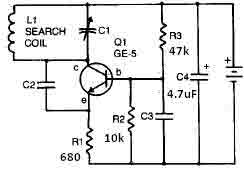
This metal detector circuit needs to be powered using a 9 volts power supply (DC) or a 9 volts battery. The C1 capacitor is a variable capacitor with a value of 365 pF, C2 is a 100 pF silver...
Short circuits in the tracks, points, or wiring are almost inevitable when building or operating a model railway. Although transformers for model systems must be protected against short circuits by built-in bimetallic switches, the response time of such switches...

The driving circuit depicted in Figure 18-12 consists of a connection between the driving portion, the microcontroller, and the air conditioning operation components of the bridge. The microcontroller's digital signal levels from ports P4.0 to P4.3 (approximately 12 feet)...