
Telephone relay

The described circuit functions as a relay activation mechanism that engages when a phone receives an incoming call. It is integrated across the bell circuit, which is the part of the phone responsible for ringing when a call is received. The primary component of this circuit is a relay, which serves as an electromechanical switch that can control a higher power device in response to a lower power signal.
When the phone rings, the bell circuit generates a voltage that is detected by the relay. This voltage energizes the relay coil, causing the relay contacts to close. The closing of the contacts can then be used to power various devices such as bells, sirens, buzzers, or lamps. The inclusion of delay contacts allows for the operation of these devices with a predetermined time delay, providing flexibility in the timing of the alert.
For schematic representation, the circuit typically includes a relay with a coil connected in parallel to the phone's bell circuit. The relay contacts can be configured as normally open (NO) or normally closed (NC), depending on the desired operation of the connected device. A diode may be added in parallel with the relay coil to prevent back EMF from damaging other circuit components when the relay is de-energized.
Overall, this circuit design is straightforward yet effective for enhancing alert systems associated with incoming phone calls, providing additional notification options beyond the standard ringing sound.Connected across the bell circuit of phone, this circuit closes a relay when the phone is ringing Use the delay contacts to actuate any bell, siren, buzzer or lamp.
Related Circuits
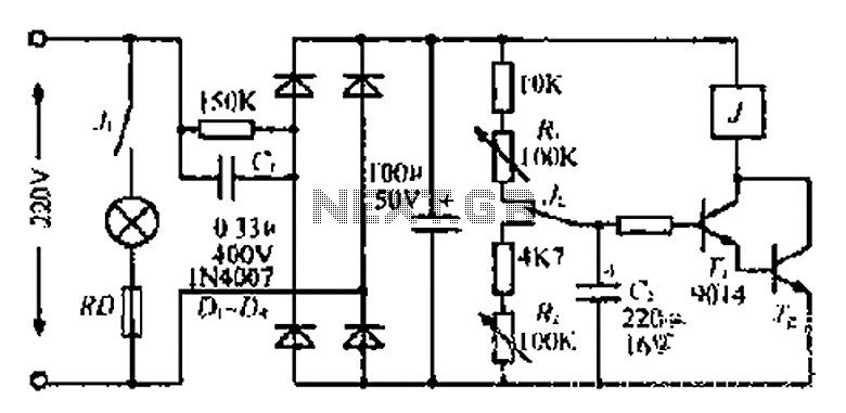
220V mains electricity is sent through a 0.33 µF capacitor (Ci) and a 50 kΩ resistive drop. A bridge rectifier composed of diodes D1 to D4 converts the AC voltage to DC. After passing through a 100 µF capacitor...
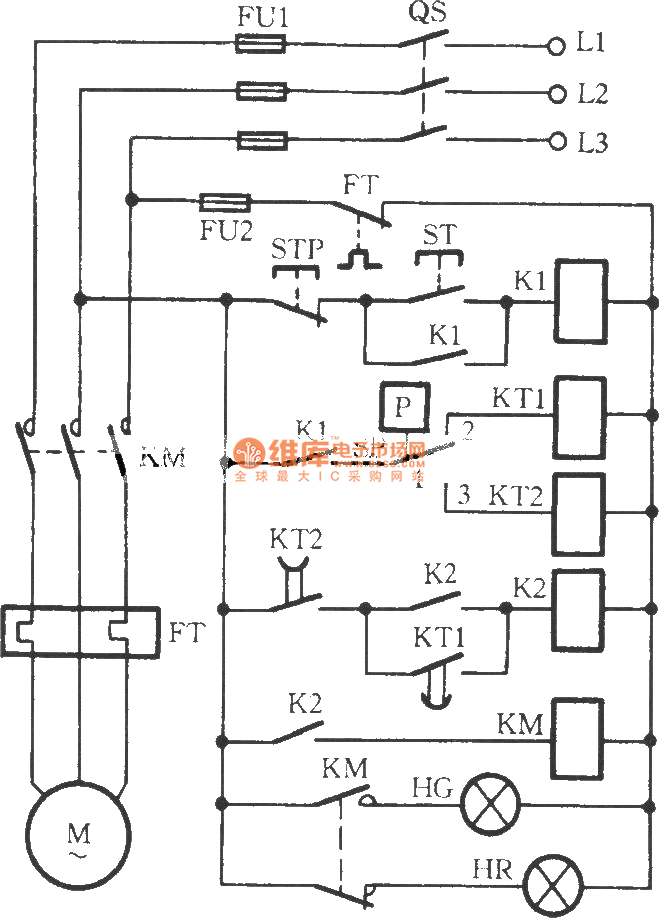
The circuit utilizes two time relays, KT1 and KT2, which are connected in series with the contacts of an electric contact pressure gauge (SP). This configuration helps to mitigate issues such as tremors or sparking that may occur due...
A simple thermostat circuit that can control a relay to supply power to a small space heater through the relay contacts. The relay contacts must be rated above the current requirements for the heater. Temperature changes are detected by...

This design uses a smart card to enable a relay. A Nutchip recognizes its mating smart card among thousand similar ones, because you choose the code to be programmed in the card's memory. No specialized knowledge is necessary, as...
This circuit below shows a teleremote circuit that enables the switching on and off of appliances through telephone lines. The teleremote circuit utilizes a telephone line as a medium for controlling electrical appliances from a distance. The primary components...
The Link circuitry is simple and efficient, employing just two integrated circuits (ICs), a few transistors, and common components. It operates on 12 volts and is easy to assemble. This intercom system can connect various locations such as the...