
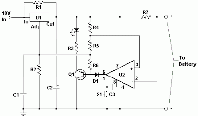
2.5 V Lead-Acid Battery Charger
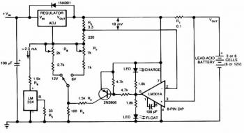
The 1.5 V Lead-Acid Battery Charger Circuit is designed to efficiently charge lead-acid batteries while ensuring optimal voltage regulation and protection against overcharging. The circuit utilizes a voltage comparator that monitors the battery voltage and adjusts the output of the voltage regulator accordingly.
In this configuration, the voltage comparator is typically set up with a reference voltage that corresponds to the fully charged state of the battery. When the battery voltage drops below this reference level, the comparator activates the voltage regulator, allowing current to flow into the battery for charging. Conversely, once the battery reaches the desired voltage threshold, the comparator's output will signal the regulator to cease charging, thereby preventing damage to the battery from overvoltage conditions.
Key components in this circuit may include a voltage regulator IC, such as the LM317, which can be adjusted to output the necessary charging voltage. Additionally, protection diodes can be incorporated to safeguard against reverse polarity and to prevent current from flowing back into the circuit when the power source is removed.
The circuit may also include filtering capacitors to stabilize the output voltage and ensure a smooth charging process. A current limiting resistor can be added in series with the output to control the charging current and further protect the battery.
Overall, this simple yet effective circuit design facilitates safe and reliable charging for 1.5 V lead-acid batteries, making it suitable for various applications where such battery technology is employed.The following circuit shows about 1.5 V Lead-Acid Battery Charger Circuit Diagram. Features: comparator s output controls the voltage regulator, .. 🔗 External reference
Related Circuits
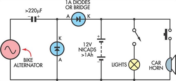
This simple circuit enables a 12V battery pack to be charged using a bike generator. The generator has a power rating of 3W, and this voltage multiplier circuit is designed to enhance the output voltage. The circuit employs a voltage...
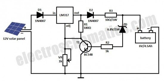
This is a solar charger circuit designed to charge Lead Acid or Ni-Cd batteries using solar energy. The circuit captures solar energy to charge the batteries. The solar charger circuit typically consists of several key components, including a solar panel,...
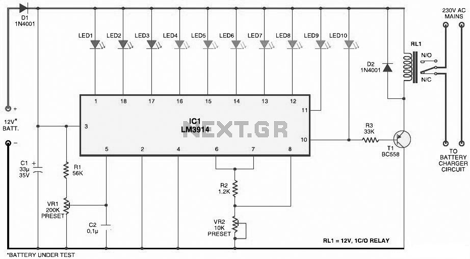
This document presents a circuit diagram for a simple and easy-to-construct battery level indicator. Typically, in mobile phones, battery levels are shown in either dot or bar format, allowing users to easily recognize the battery status. The battery level indicator...
The circuit is designed to be powered directly by a power supply, which is why it does not include a transformer, rectifier, or filter capacitors in the schematic. However, the addition of these components is possible. To operate the...
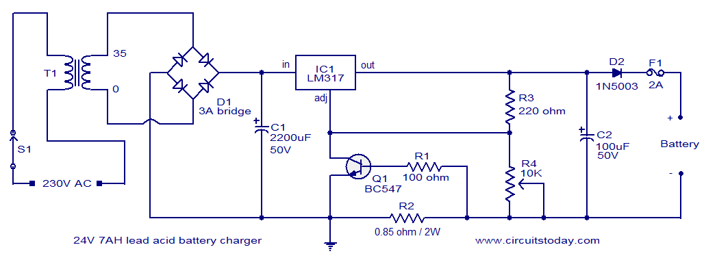
This lead-acid battery charger circuit is designed based on a request from Mr. Devdas C. His requirement was for a circuit that could charge two 12V/7AH lead-acid batteries connected in series. He did not specify the number of cells...
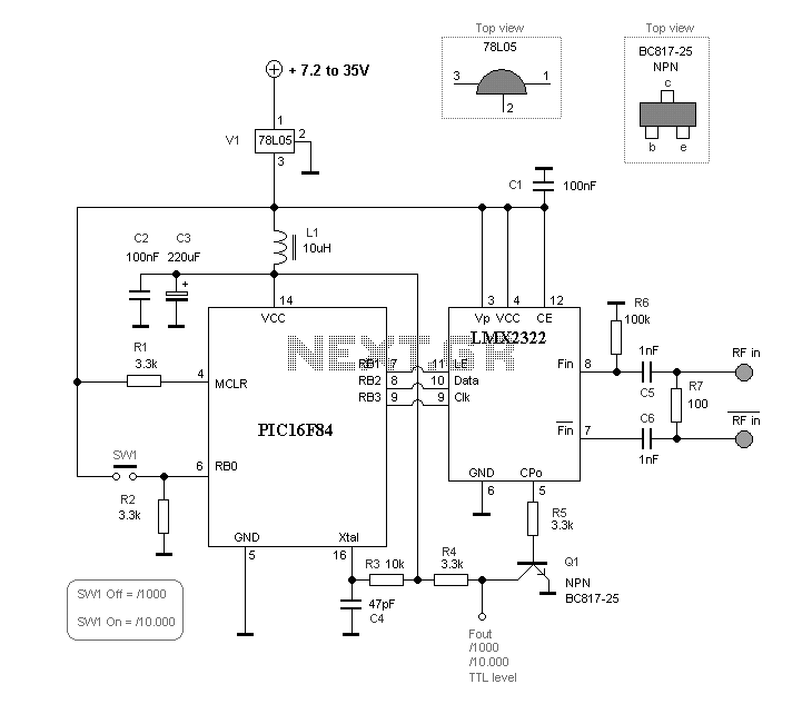
This project will describe a prescaler which will work up to 2.5GHz and with very high input sensitivity. The prescaler will divide the input frequency with either 1000 or 10.000. The divided output signal is 0/5 volt and can...
Warning: include(partials/cookie-banner.php): Failed to open stream: Permission denied in /var/www/html/nextgr/view-circuit.php on line 713
Warning: include(): Failed opening 'partials/cookie-banner.php' for inclusion (include_path='.:/usr/share/php') in /var/www/html/nextgr/view-circuit.php on line 713