
Time base using a delay circuit touch lamp
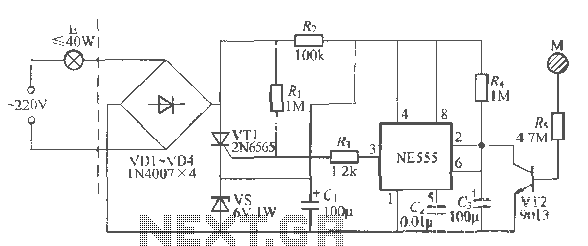
The NFA.55 timebase circuit delay type light touch switch is designed to replace traditional mechanical switches with a modern, efficient solution. This circuit utilizes a combination of resistors, capacitors, and semiconductor devices to achieve its functionality. The NE555 timer IC serves as the core of the timebase circuit, providing precise timing capabilities that allow for the delay feature of the switch.
Upon initial activation, the circuit remains in a stable state, with the thyristor VT1 in a non-conducting state, preventing the lamp E from lighting. The touch-sensitive electrode sheet M is strategically placed to detect user interaction. When the user touches M, a small leakage current flows through resistor R, which biases diode VT2 into conduction. This action triggers the NE555 timer by sending a negative pulse to its input, effectively starting the timing sequence.
The output of the NE555 timer raises the gate potential of thyristor VT1, allowing it to conduct and power the lamp E. The rapid discharge of the stored charge through VT2 ensures that the circuit responds quickly to the touch, providing immediate feedback in the form of light. Once the touch is removed, VT2 turns off, and the circuit begins to reset. The charging time constant dictated by R and C determines how long the lamp E remains lit after the touch is released.
The design also incorporates safety features, ensuring that the power rating of the connected load does not exceed 40W, which protects the components from overheating and potential damage. This thoughtful design allows for a seamless integration into existing systems, providing an effective solution for modern lighting control while maintaining compatibility with traditional wiring setups.Using a wire connection, use NFA.55 timebase circuit delay type light touch switch, it can directly replace ordinary mechanical switch, without having to change the original interior wiring. The circuit is powered back with good hoof Chapter 96 cases, especially on} U F is lit or put out the lights off, the circuit can always output a voltage fiV steady stream education for state-based circuit NF, 155 electricity. Usually, NE5ji in a stable state, feet lose thirty low grain lrril tube VT1 shake the f J is R, the wear of the clamp level, VTI curse off, the lamp E does not shine.
When the hand touch the electrode sheet M, the body leakage current through R, Wang injection diode VT2 base enables rapid VT2 conduction, which is equivalent to the trigger terminal feet NE555's input a negative pulse, time base circuit busied, foot jump into supplier level. Therefore, the thyristor VT1 gate potential elevation, VT1 get the trigger voltage and Ji Tong, E powered lamp light.
At the same time, G stored charge through VTZ fast relief. After leaving the people at M, VT2 off recovery, 6V DC power on by R; the G Free electricity, so f, both ends of the potential rising. When rose 2 / 3VDO That 1V, when the base circuit is reset, pin restore low, wri lost trigger voltage when the AC zero crossing that is turned off, the lamp E goes out.
In addition to the delay time of the circuit R. , C, has a charging time constant curse, but also by the length of time there is a touch off. When a finger touch time than K, G can store sufficient electrical discharge leaning, the "C. charge to 4V asked on the long, corresponding lamp lighting time will be longer. In addition, the load capacity of the circuit but also by steady pressure pipe vs dissipated power constraints, so the bulb E power not more than 40W.
Related Circuits

Originally, the tank cost around Php 400 but was later sold for approximately a hundred pesos less. Recognizing a great deal, the decision was made to purchase the toy. Opening the toy proved to be somewhat challenging. The track...
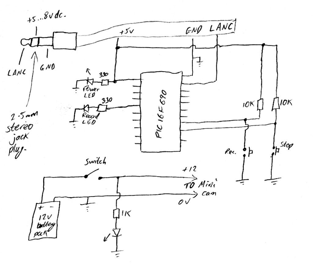
Inexpensive PIC-controlled helmet camera utilizing Sony LANC, suitable for extreme sports. This guide will demonstrate how to create an affordable helmet camera. The proposed electronic schematic involves a PIC microcontroller interfaced with a Sony LANC (Local Application Control Bus) to...
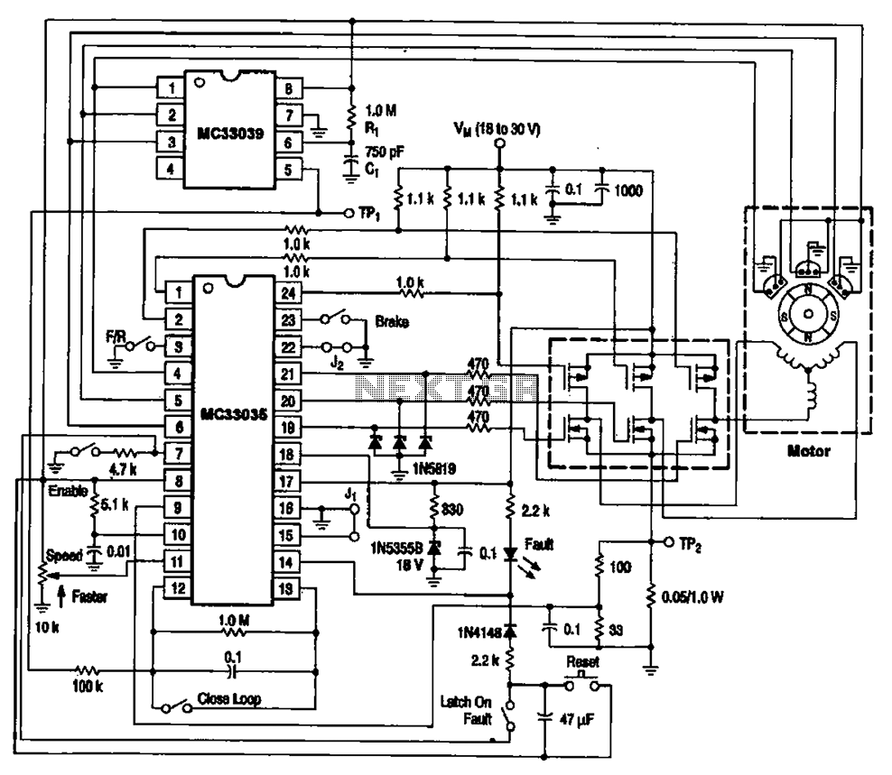
The brushless DC motor control circuit utilizing the MC33035 and MC33039 chips employs a combination of control circuits as illustrated in the figure. The primary components include the MC33035 motor control chip, the MC33039 brushless motor adapter, field effect...
Tools that feature the equivalent of a professional, easy-to-use, cheaper, and, more importantly, safe for use. They are designed for checking and identifying AC voltages of 220 Volt or 120 Volt. The tools mentioned are essential for ensuring electrical safety...
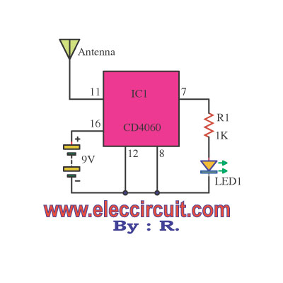
This circuit is designed to detect incoming calls on a cellular phone, even when the phone's ringer is turned off, by utilizing a flashing LED. The device should be positioned a few centimeters away from the cellular phone, allowing...
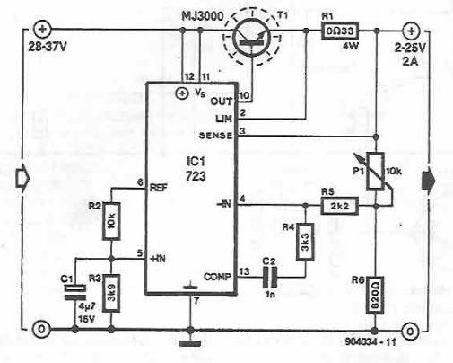
A simple variable power supply circuit can be designed using the LM723 regulator, which provides a maximum current of up to 2A and a variable voltage range between 2 and 25 volts. The LM723 voltage regulator is an integrated circuit...