
Metal detector with 555
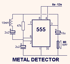
The circuit operates on the principle of inductance variation in response to the presence of a magnetic field. The core component is a 10mH choke, which is an inductor designed to resist changes in current. When a magnet approaches the choke, the magnetic field interacts with the inductor, resulting in a change in inductance. This change affects the resonant frequency of the circuit, which can be detected and measured.
The circuit typically includes a signal generator, which produces an oscillating signal at the resonant frequency of the inductor. The output from the inductor is fed into a frequency detection circuit, which could be implemented using a microcontroller or a dedicated frequency counter. The detection circuit monitors the frequency of the output signal and triggers an alert or activates a response mechanism when a significant deviation from the baseline frequency is detected.
To enhance sensitivity and reduce false positives, additional components such as capacitors may be included to form a resonant LC circuit with the inductor. The values of these components can be adjusted to fine-tune the circuit's response to specific magnetic fields or metal types. A comparator circuit may also be integrated to provide a clear digital output based on the detected frequency change, allowing for easy interfacing with other electronic systems or alarms.
This type of metal and magnet detection circuit can be utilized in various applications, including security systems, industrial automation, and proximity sensing in consumer electronics.This circuit detects metal and also magnets. When a magnet is brought close to the 10mH choke, the output frequency changes. 🔗 External reference
Related Circuits
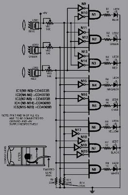
This circuit is capable of sensing eight colors: blue, green, and red (primary colors); magenta, yellow, and cyan (secondary colors); along with black and white. It is designed based on the principles of optics and digital electronics. The object...
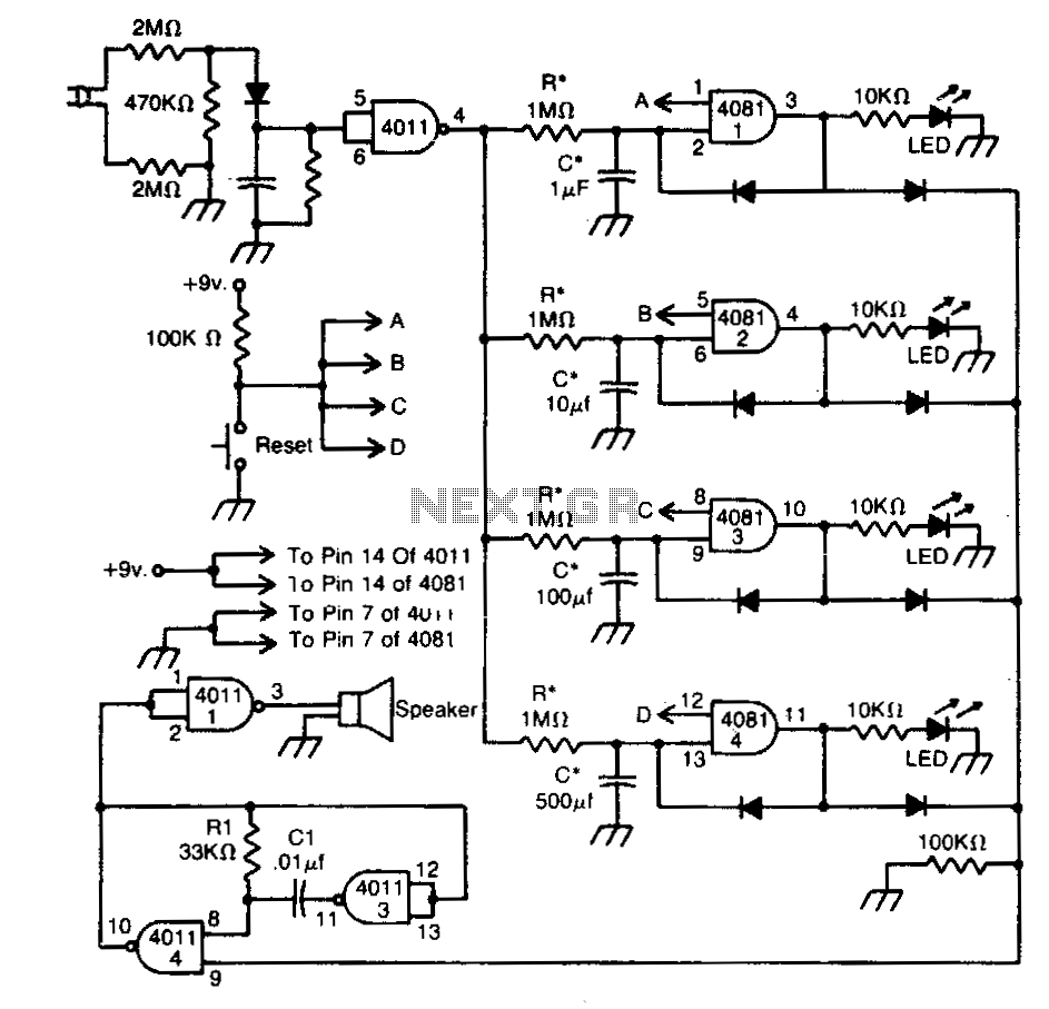
This circuit indicates that a power outage occurred for 1, 10, 100, and 500 seconds based on the values provided for R* and C*. After a power failure, the circuit can be reset by pressing the Reset button. The described...

This is a simple smoke alarm circuit using a timer IC, the NE555. The circuit operates by illuminating a Light Dependent Resistor (LDR) with a lamp. When smoke obscures the light from the lamp, the resistance of the LDR...
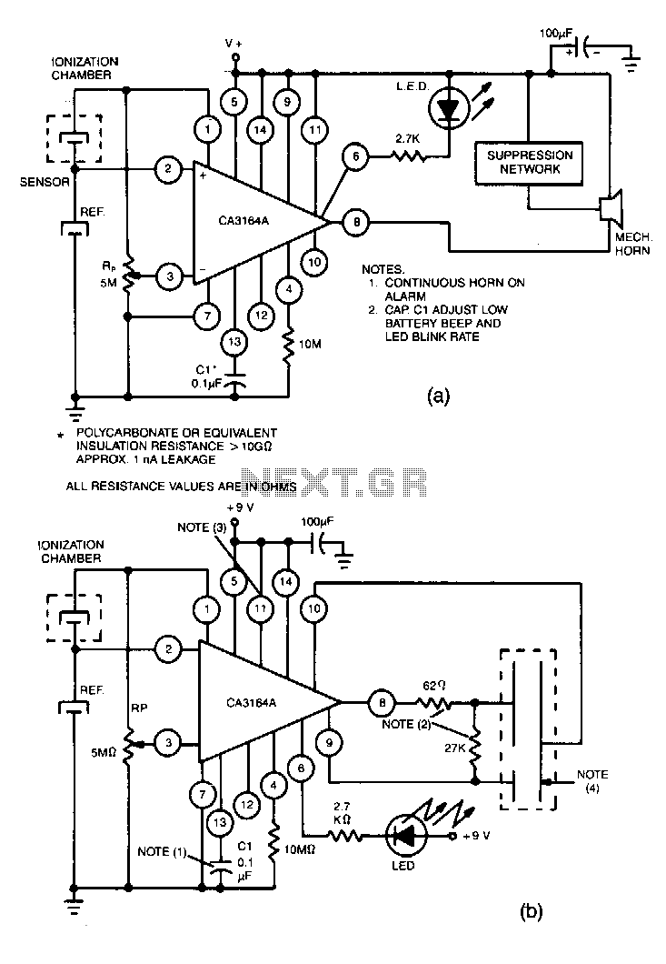
Utilize the CA3164A BiMOS detector/alarm system for operation as a smoke detector with an electromechanical horn (refer to Fig. 40-la). The output driver at terminal 8 is employed, utilizing a large npn transistor Q3 with an active pull-up, while...
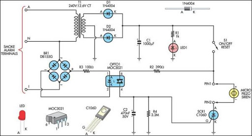
This alarm circuit is designed to monitor a mains-powered smoke detector located in a shed used for dog kennels. It ensures complete isolation from the mains, allowing low-voltage (12V) cabling to run to the alarm circuit, which is situated...
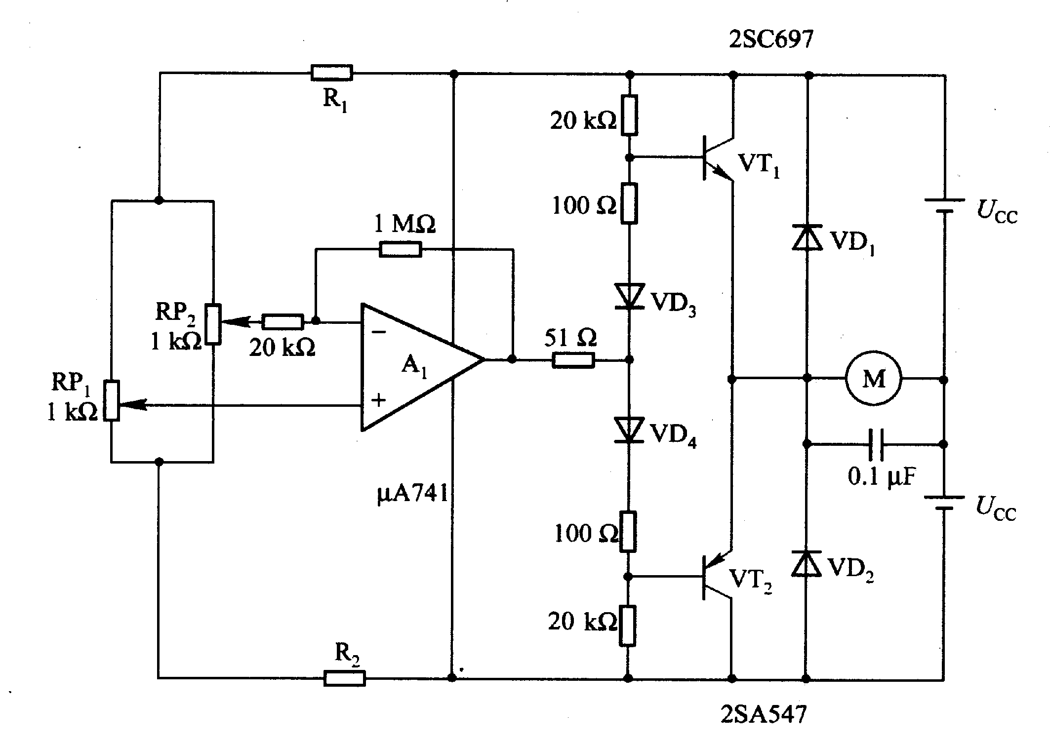
Figure 2-32 (a) illustrates the time control diagram for a motor operated by switch S1. When S1 is set to position 1, the power driver circuit supplies current to the motor, enabling it to run. When S1 is switched...
Warning: include(partials/cookie-banner.php): Failed to open stream: Permission denied in /var/www/html/nextgr/view-circuit.php on line 713
Warning: include(): Failed opening 'partials/cookie-banner.php' for inclusion (include_path='.:/usr/share/php') in /var/www/html/nextgr/view-circuit.php on line 713