
Cheap positive and negative circuit
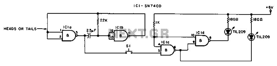
The circuit operates by utilizing a switch (S1) that plays a crucial role in controlling the flow of current within the system. When the current reaches a predetermined threshold, S1 engages the shut-off switch, effectively interrupting the circuit and halting further current flow. This mechanism is essential for preventing potential damage to components by avoiding overcurrent situations.
In a typical application, S1 can be integrated into various electronic devices to ensure safety and reliability. The design may include additional components such as resistors, capacitors, or diodes to enhance performance and protect against voltage spikes or surges. The shut-off switch can be designed to operate either automatically or manually, depending on the requirements of the specific application.
The configuration of the circuit should be carefully considered, taking into account the expected current ratings and the characteristics of the components used. Proper selection of materials and components will ensure that the circuit functions effectively and safely under various operating conditions. Circuit Description: S1 promote the release of the current reaches the shut-off switch.
Related Circuits
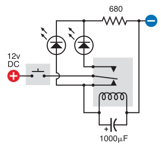
The intended result is for the relay to oscillate and the LEDs to flash when the button is pressed. However, when the button is pressed, the leftmost LED lights constantly, and nothing else happens. There is voltage across the...
NiCd battery charger schematic and description. This NiCd battery charger circuit can charge 12V, 6V, and 9V battery packs. The NiCd battery charger circuit is designed to efficiently charge nickel-cadmium (NiCd) batteries, specifically those with voltage ratings of 12V, 6V,...
This circuit is designed to power a lamp or other appliance for a specified duration of 30 minutes, after which it automatically turns off. It is particularly useful for nighttime reading, as it can turn off a bedside lamp...
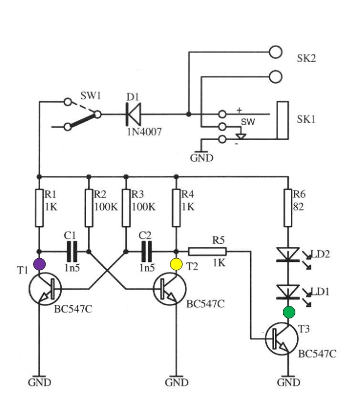
The schematic circuit presented below illustrates an infrared transmitter. The infrared beam is emitted in a nearly line-of-sight manner towards another device equipped with an infrared receiver. The displayed waveforms represent the output voltages from two intermediate stages (purple...
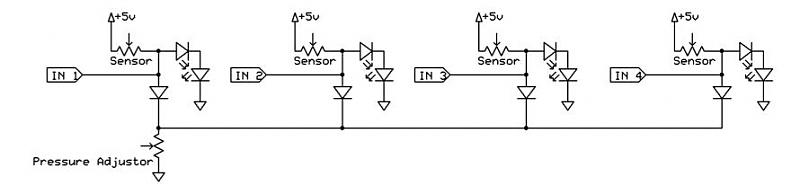
A dance pad consists of four pressure sensors (up, down, left, right). A USB controller has already been created for the dance pad, and the next step involves connecting the actual sensors. The intention is to pull the input...
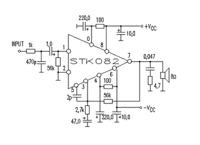
This amplifier circuit is suitable for home power audio devices. The STK082 amplifier specifications suggest that it can operate with supply voltages of up to ±43V. However, it is advisable to use no more than ±25V for 8-ohm loads,...
Warning: include(partials/cookie-banner.php): Failed to open stream: Permission denied in /var/www/html/nextgr/view-circuit.php on line 713
Warning: include(): Failed opening 'partials/cookie-banner.php' for inclusion (include_path='.:/usr/share/php') in /var/www/html/nextgr/view-circuit.php on line 713