
Positive Pulse Pulse Stretcher

The described pulse stretcher circuit utilizes an operational amplifier (op-amp) configured in two stages to achieve the desired pulse stretching effect. The first stage, comprising op-amp U1A, is configured as a voltage follower, which ensures that the output voltage follows the input voltage without any inversion or gain, thus providing high input impedance and low output impedance. This configuration is crucial for driving the diode D1 and capacitor C2 effectively.
When a pulse is applied to the input of U1A, the output voltage reaches the peak value of the input pulse, allowing capacitor C2 to charge up to this peak voltage. The charging process is rapid, enabling the capacitor to respond swiftly to changes in the input pulse amplitude. Resistors R3 and R4 are strategically placed in the circuit to control the discharge time of C2. The time constant of the discharge, which is determined by the values of R3 and R4 in conjunction with the capacitance of C2, directly influences the duration for which the output pulse is stretched.
The second stage of the circuit, comprising U1B, also operates as a voltage follower. This stage is essential for buffering the output of the pulse stretcher, ensuring that the output impedance remains low and can drive subsequent stages of the circuit without distortion or loss of signal integrity.
In practical applications, this pulse stretcher circuit is capable of stretching input pulses by a factor of up to 50 times, making it suitable for various electronic applications where pulse width modulation or timing adjustments are necessary. The ability to charge C2 to accommodate different pulse rates allows for versatility in its use, making it applicable in signal processing, communication systems, and timing circuits, where precise control over pulse duration is required. A simple pulse stretcher built with two sections of an op amp uses voltage follower U1A to drive Dl and C2. C2 charges to the peak value of pulse voltage. R3 and R4 determine the discharge time of C2 and therefore the pulse stretching. U1B acts as a voltage follower. Typically this circuit can stretch a pulse by a factor of 50. C2 can be charged to accommodate different pulse rates.
Related Circuits
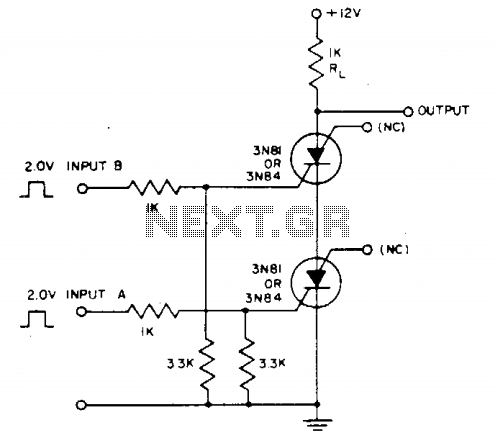
Voltage across resistor Rl is only present when inputs A and (2- to 3-V amplitude) occur simultaneously. A brief overlap of less than 1 microsecond is enough to trigger the silicon-controlled switch (SCS). Coincidence of negative inputs is detected...
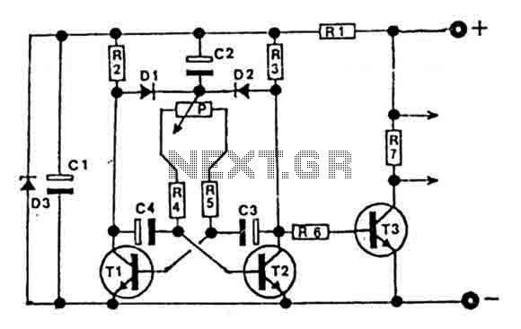
This circuit is designed for controlling motors, lamps, heating elements, and similar devices continuously from nearly zero to maximum capacity (5-95%). It utilizes impulse control for nearly lossless operation, providing almost total torque for motors. The transistor T3 must...

Fast rise-time high-voltage pulses have various applications, including EMC testing and device characterization. The circuit outlined here is a simple, cost-effective solution designed for the latter purpose. It can generate pulses ranging from 0 to 1000 V with currents...
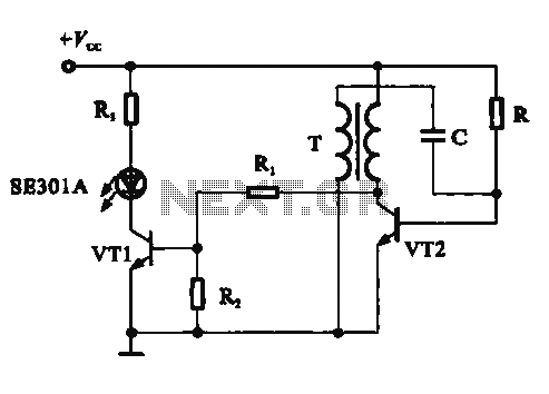
This circuit demonstrates a dynamic AC signal level display drive, which can be utilized for audio level display purposes. The AC signal detection and drive control are achieved using the BA6124 integrated circuit, along with five external colored light-emitting...
It was designed for an application in a welding machine: there are lots of bits of machinery which are cylindrical in shape and which are subjected to heavy surface wear. For instance ore crushers, and the idler and roller...
This compact device, designed primarily for modelers, provides instantaneous readings of pulse duration in milliseconds (ms). It can measure servomotor positions, typically ranging from 1 ms to 2 ms, and can also perform repetitive or non-pulsed measurements, such as...