
Power Amplifier
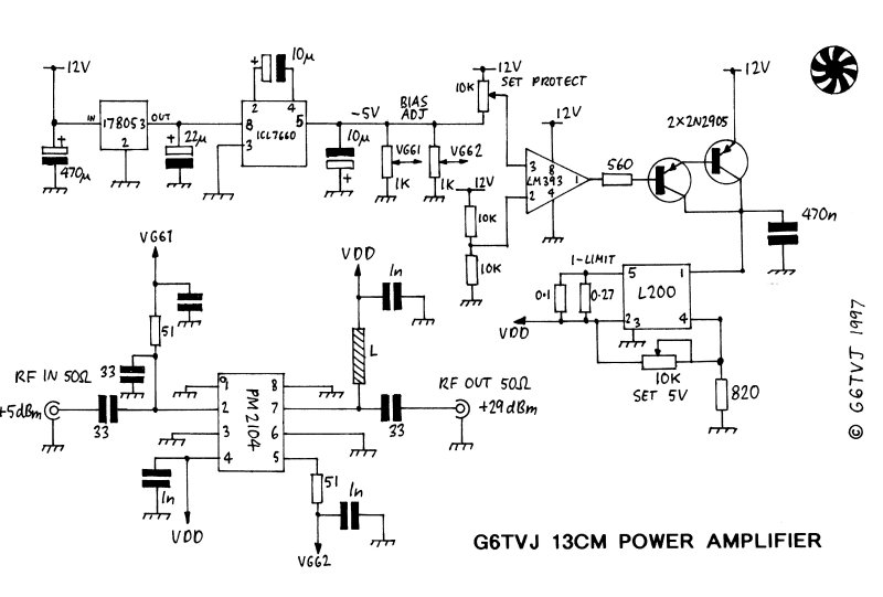
The PM2104 amplifier circuit is designed to operate efficiently within the 13 cm amateur band. The careful selection of components, including the ICL7660 for negative voltage generation and the L200 for current limiting, enhances the reliability and performance of the setup. The use of surface-mount technology allows for compact designs, but it necessitates precision in assembly, particularly in soldering the PM2104 to the PCB. The implementation of a comparator circuit serves as a safeguard against bias supply failures, ensuring the longevity of the amplifier. By adhering to the specifications outlined in the manufacturer's data sheet and performing iterative adjustments to bias voltages, optimal performance characteristics can be achieved, making the PM2104 a viable choice for applications requiring medium power amplification at 2.3 GHz and beyond.A simple synthesised 13cm ATV exciter my thoughts turned to what could be used as a power amplifier. The exciter produces about 10mW perhaps enough to drive some sort of MMIC or hybrid amplifier. The problem with 13cm is that at 2. 3 GHz and beyond devices either discreet transistors or amplifiers get very expensive. After researchinga number of manufacturers and suppliers I eventually came up with an IC amplifier costing about £40 and producing almost a watt, at these frequencies not a bad power to price ratio. The PM2104 manufactured by Pacific Monolithics is a GaAs MMIC amplifier device intended for ISM applications centred on 2.
440 GHz, the device is relatively wide band so covers the whole of the 13cm amateur band. The IC has a gain of 24 dB and runs on a supply of +5V, it also requires two negative bias supplies similar to other gas fet amplifiers. The 2104 is a surface mount device housed in a SOT8 package and heatsinked via its metalised base, it`s pritty tidly so is not recommended for newcomers to surface mount construction techniques.
All the clever stuff is done inside the PM2104 IC, fig 1 shows the circuit diagram of the amplifier. The bias supplies and positive supplies are decoupled, some 50R matching resistors and a 33p cap are also required. The device is nominally pre-matched to 50R but a 33p matching cap is needed at the input pin. The device is powered on pins 4 and 8 with 5V. Negative bias is supplied to pins 2 and 5. An ICL7660 DC to DC converter chip is used to generate the negative supply in a similar manner to what is used in some of the Microwave Committee 3cms units.
A simple comparator circuit is used to detect the presence of the bias supplies and then switch on the +5V VDD supply to the IC. If the bias voltage fails the IC may be destroyed so the comparator is needed to protect it. As a second measure the L200 5V regulator incorporates a current limit set to about 600 mA, I have not proved the action of this circuit but after the touch and go action of soldering the IC in and the £40 whole in my pocket I thought I would put it in.
The bias generator, comparator, and regulators can be built on stripboard as convenient, only mild heatsinking is required. A standard fibreglass double sided PCB is etched to the pattern shown, the layout comes from the manufacturer`s data sheet.
The base of the IC is metalised and must be soldered down to the board to form a heatsink. First tin the underside, solder down the pins and finally solder down the base by applying the iron to each side. The operation of mounting the IC is very tricky so not recommended for people without previous experience of working with surface mount devices.
The other components can be added including several via pins which help earth the device. The PCB is then mounted in a tinplate box and fitted with SMA connectors in a similar way to how the RSGB microwave committee 3cm amplifiers are constructed. The data sheet suggests that pin 2 should be set to -1. 2V and pin 5 set to -1. 5V, it is best to start with more negative bias and reduce them carefully while monitoring the supply current and power out.
It is worth checking the action of the L200 current limit first with a dummy load. The protection circuit can be set up by adjusting the protect pot until the VDD supply just switches on (Best done before connecting the VDD supply to the 2104). I found that I could get the best efficiency with slightly different values of bias. By comparing the DC power in and RF power out the bias can be tweaked for minimum power dissipation of the PM2104.
The values I ended up with were -1V and -2. 2V for pins 2 and 5 respectively. The attainable output power should be up to about 800mW, +29 dBm with 5 mW of drive. The PM2104 runs warm to the touch in operation. In the absence of a better solution for attaining medium levels of power at these frequencies the PM2104 does OK. The 🔗 External reference
Related Circuits
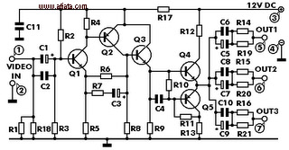
This electronic circuit is a video signal amplifier that provides a broad bandwidth amplifier with a capacity of 5 MHz. It is designed to take video signals from a VCR and amplify them adequately to drive up to three...
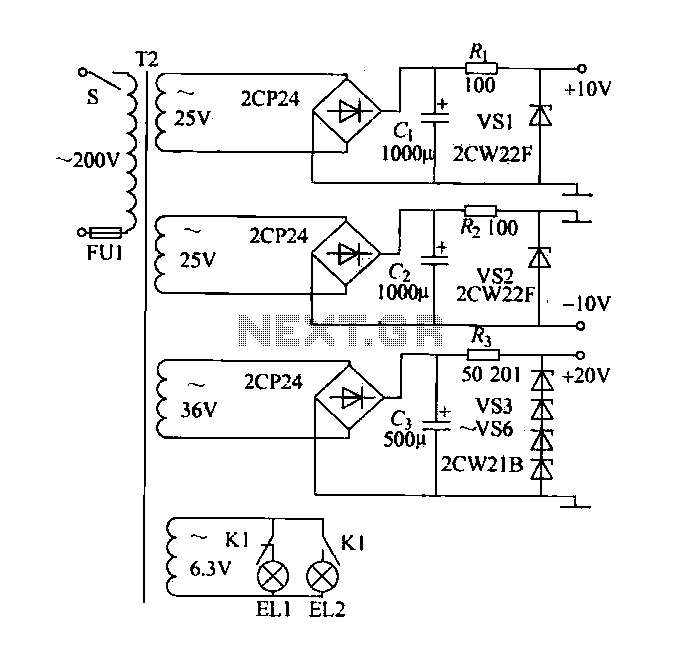
A DC power supply with a shunt, rectifier, filter, current limiting, and voltage regulation, providing 10V voltage outputs. The circuit is simple and low cost, designed to meet the requirements of various applications. Additionally, it features a 3V indicator...
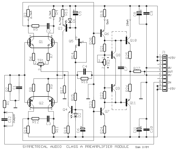
The circuit was designed to produce a preamplifier with symmetrical audio input while the output operates in Class A type. Preamplifier (pre-amp) a device... The circuit in question is a preamplifier designed to handle symmetrical audio inputs, which ensures that...
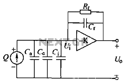
A charge amplifier is an effective device for measuring punch hits. This amplifier utilizes a negative feedback capacitor in conjunction with a high-gain operational amplifier. The amplifier operates with minimal shunt, relying primarily on the feedback capacitor's charge (q...
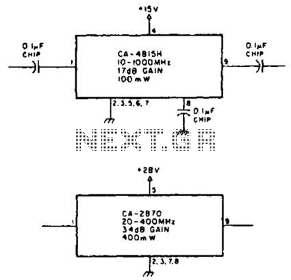
Using TRW part number CA-815H, a 17 dB gain amplifier capable of delivering 100 mW over a frequency range of 10 to 1000 MHz can be constructed. Additionally, the CA-2870 can provide 0.4 W with a gain of 34...
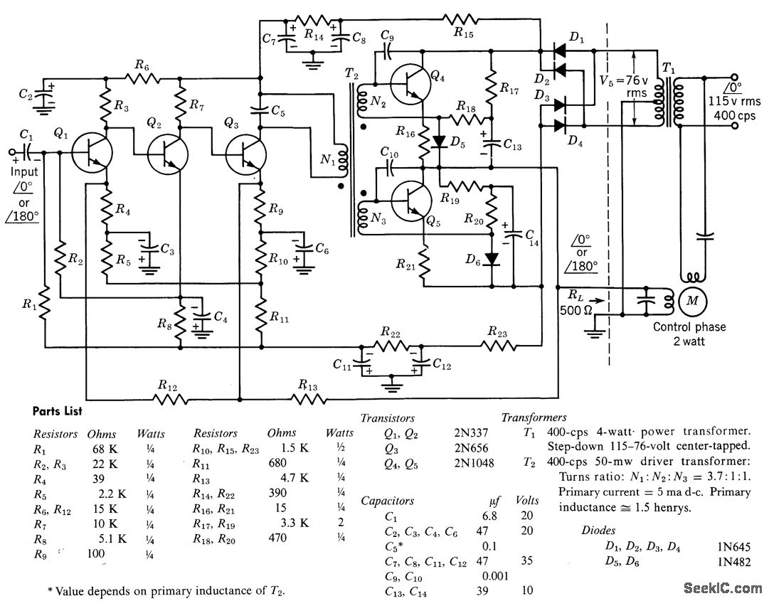
The circuit comprises a direct-coupled preamplifier and driver stages, featuring significant direct current (d-c) feedback to stabilize bias conditions. The voltage gain of the amplifier, when the feedback loop is closed, is 10,000. The overall efficiency of the circuit...