
Power booster
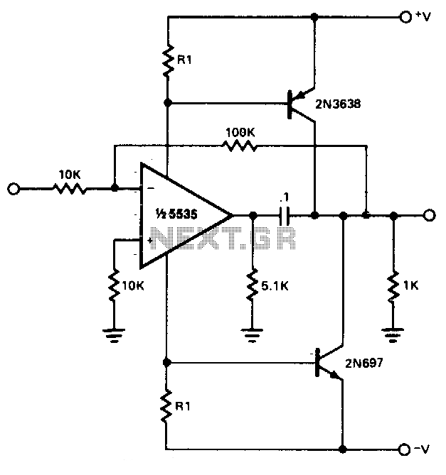
The power booster circuit primarily employs the NE5535 operational amplifier, which is known for its high performance in terms of bandwidth and low distortion. This device is well-suited for applications where moderate load driving capability is essential. The NE5535 features a dual operation, allowing for flexibility in design configurations.
When substituting the NE5535 with alternative amplifiers, it is crucial to consider the supply current (Icc) specifications of the new amplifier. Each amplifier may have different current requirements, which will impact the resistor values in the circuit. Specifically, R1 must be recalculated to ensure that the circuit operates within the desired parameters and maintains stability.
To determine the value of R1, the following expression should be used:
\[ R1 = \frac{V_{supply} - V_{out}}{I_{cc}} \]
Where:
- \( V_{supply} \) is the supply voltage provided to the circuit.
- \( V_{out} \) is the output voltage level required for the load.
- \( I_{cc} \) is the supply current needed by the amplifier being used.
This formula allows for precise tuning of the resistor to accommodate the specific operational characteristics of the selected amplifier, ensuring optimal performance of the power booster circuit. Additionally, careful attention should be paid to the power ratings of all components to prevent overheating and ensure reliability during operation.Power booster is capable of driving moderate loads. The circuit as shown uses a NE5535 device. Other amplifiers may be substituted only if R-l values are changed because of the Icc current required by the amplifier R1 should be calculated from the following expression:. 🔗 External reference
Related Circuits
Measure the voltage across the 1k resistor connected to the input stage and Vcc. The DC voltage should be approximately 2 volts, or 2 mA of current flowing through this resistor. For instance, if Vcc is at 24 volts,...
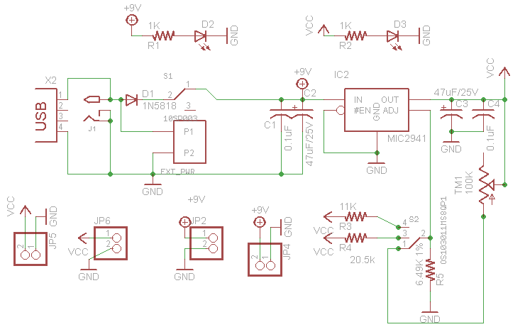
This project outlines the design of a very low dropout adjustable power supply. A reliable power supply is crucial for electronic projects. Although numerous existing designs for adjustable power supplies are available, this particular design introduces enhancements that increase...
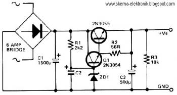
This circuit can be utilized in applications requiring high current and low ripple voltage, such as in high-powered Class AB amplifiers where high-quality audio reproduction is essential. Q1 and Q2, along with resistor R2, function as a power Darlington...
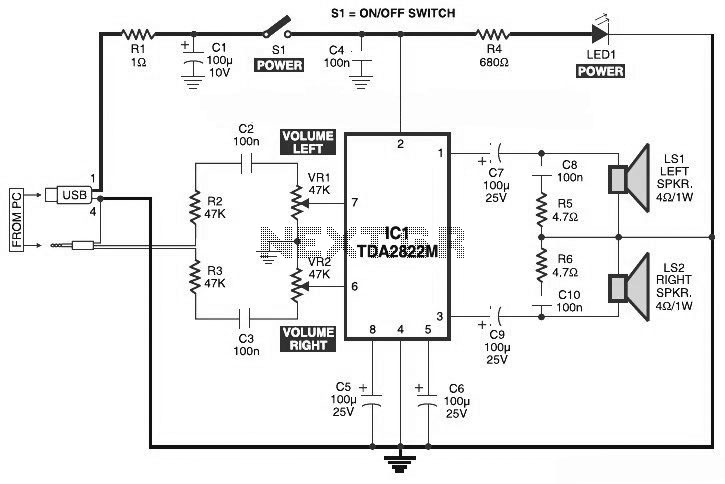
This is the circuit diagram of a USB-powered computer speaker, commonly known as multimedia speakers for PCs. The circuit features a single-chip design, operates on a low-voltage power supply, and is compatible with USB power from a computer. The USB-powered...
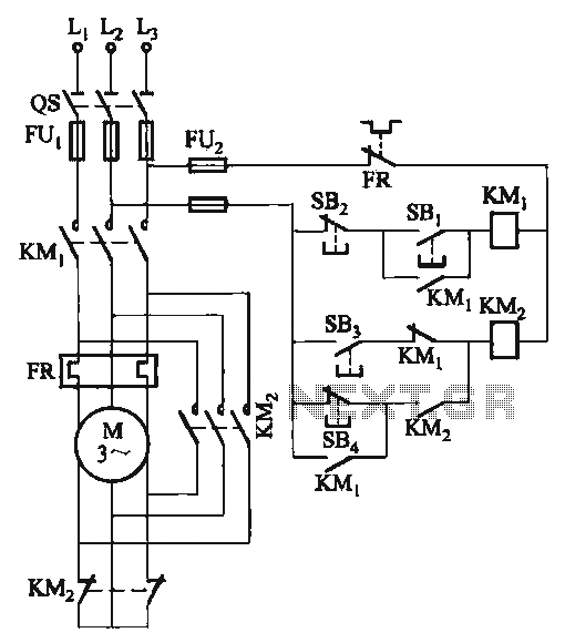
The C620 lathe Y-conversion includes a power-saving circuit designed for controlling the motor's reversing functionality. This system is applicable to machines such as the C620, C630, and CW61100A lathes, as well as radial drilling and milling machines. The C620 lathe...

The circuit is designed to regulate a dual power supply that provides +12V and -12V from the AC mains. Such a power supply is an essential tool for an electronic hobbyist's workbench. The schematic of the circuit includes components...