
power supply schematic

The electronic rectification circuit described employs a gyrator configuration to enhance the effectiveness of the smoothing capacitors. The primary objective of this design is to eliminate the need for large electrolytic capacitors, which are often cumbersome and costly. Instead, the circuit leverages the properties of a transistor, specifically the 2N3055, to amplify the effective capacitance seen at the output.
In this configuration, capacitor C1 serves as the input capacitor, rated at 470µF, which is relatively small compared to traditional designs. The gyrator's functionality is rooted in the transistor's current gain (HFE), which allows the effective capacitance at the output to be significantly increased. For example, with an HFE of 50, the effective capacitance provided at the output is equivalent to a 5000µF capacitor, thus greatly improving the circuit's performance in terms of ripple reduction.
Capacitor C2, rated at 100µF, plays a crucial role in this enhancement. The circuit's output voltage (Vreg) experiences reduced ripple, improving the overall stability and reliability of the power supply. The load, drawing approximately 400mA, experiences a notable reduction in ripple voltage when the output is taken from the emitter of the transistor, compared to the direct output from the rectifier.
The transient response of the circuit is also noteworthy, as it stabilizes within a few hundred milliseconds after a load is applied. This quick stabilization is essential for applications where consistent voltage levels are crucial. The design's efficiency in using smaller capacitors not only reduces costs but also optimizes space in electronic assemblies, making it an attractive choice for modern electronic power supply designs.An electronic recitification circuit. The use of large, heavy and expensive electrolytic capacitors is avoided, being replaced by an active transistor in this gyrator circuit. To avoid excess ripple output on a power supply feeding a heavy load, usually a large value capacitor is chosen following the rectifier.
In this circuit, C1`s value is only a 470uF. The gyrator circuit works on the principle that the value of input capacitance at the base-emitter terminals of a transitor is effectively multiplied by the static forward current gain, HFE of the transistor. In this circuit C2, a 100uF capacitor is effectively magnified at the ouput ( Vreg ). If you assume a dc current gain, HFE of 50 for the 2N3055 power transistor, then the effective value of the smoothing capacitor would be 50x this value; or be the same as using a 5000uF capacitor without the power transistor.
The graph below shows the output voltage and current through the load :- The load draws nearly 400mA. With the output directly from the rectifier there is about 5v pk-pk ripple in the output. Using the output at the emitter of the transistor things are much better. The circuit will take a few hundred milliseconds for the output voltage to stabilize and reach maximum value.
The advantages are that a smaller, less costly reservoir capacitor can be used with this circuit to give a high quality 🔗 External reference
Related Circuits
The schematic for an infrared burglar alarm circuit is depicted in Figure 1. The infrared transmitter operates as a multivibrator with an oscillation frequency of 40 kHz, utilizing the NE555 integrated circuit (IC2), along with resistors R1 and R2...
The two circuits below illustrate opening a relay contact a short time after the ignition or light switch is turned off. The capacitor is charged and the relay is closed when the voltage at the diode anode rises to...
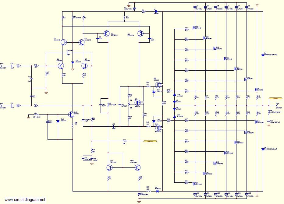
This amplifier is suitable for various applications that demand high power, low noise, minimal distortion, and superior sound quality. Examples include subwoofer amplifiers, front-of-house (FOH) stage amplifiers, and individual channels of high-powered surround sound amplifiers. For a detailed explanation...
The digital lock shown below uses 4 common logic ICs to allow controlling a relay by entering a 4 digit number on a keypad. The first 4 outputs from the CD4017 decade counter (pins 3,2,4,7) are gated together with...
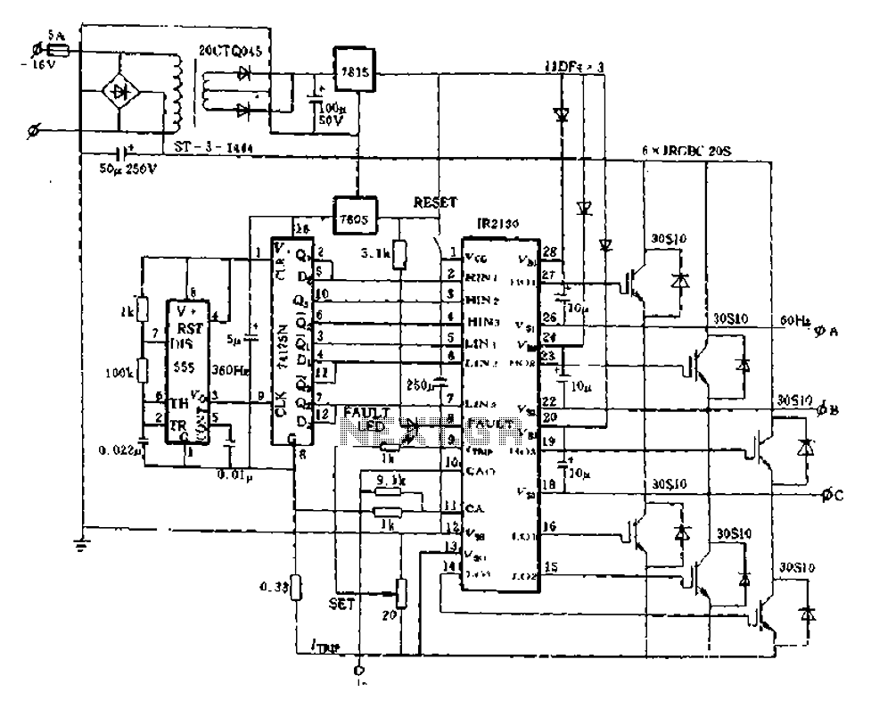
The application of the aforementioned advantages allows the IR2130 to be effectively utilized for DC cut crossing speed, DC servo systems, three-phase power inverters, and switching power supplies. Additionally, it is applicable in inverter power supplies, uninterruptible power supplies...

In electronic technology, the triode utilizes a variety of general components and parts. The parameters of the triode and numerous electrical parametric measurement schemes are closely related to measurement results. Therefore, in electronic design, the base pin, typological judgment,...