Power Buzzer
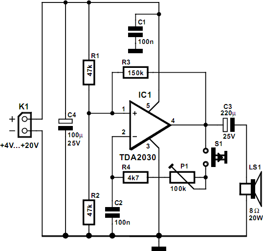
On average, how often do you need to call family members each day to inform them that dinner is ready or that it's time to leave? Typically, the person being called is in a different room, such as a hobby room or bedroom. A powerful buzzer in that room, paired with a pushbutton located at the bottom of the stairs or in the kitchen, could be very helpful in such situations. The core of this circuit utilizes IC1, a TDA2030, which features built-in thermal protection, ensuring longevity. Resistors R1 and R2 apply a voltage equal to half the supply voltage to the positive input of the op-amp. Resistor R3 provides positive feedback. The combination of capacitor C2, resistor R4, and trimmer potentiometer P12 determines the oscillation frequency of the circuit, which can also be adjusted using P1. There is no volume control, as the objective is to ensure attention when the push-button S1 is pressed. The entire circuit should be positioned where the push-button is accessible, while the loudspeaker can be strategically placed in the bedroom or other suitable locations. It is advisable to connect the loudspeaker using speaker cable, as normal bell wire may cause significant power loss if the loudspeaker is placed far away. The loudspeaker should handle a continuous power of at least 6 W when using a 20-V supply voltage. Power output decreases as the supply voltage drops, following the formula P = Urms² / RL. The power supply for this circuit is not overly critical but must provide sufficient current, with a recommended nominal value of around 400 mA at 20 V. At 4 V, the current requirement is approximately 25 mA. A suitable power supply can likely be found in a hobby room, or an affordable power supply design may be located in a circuits archive.
This circuit functions as an alert system designed to notify family members in different rooms when an event occurs, such as dinner being ready. The TDA2030 integrated circuit serves as the primary component, providing amplification and thermal protection to enhance reliability. The circuit's operational amplifier configuration is established through resistors R1 and R2, which set the input voltage, while R3's feedback mechanism ensures stability and responsiveness.
The oscillation frequency of the buzzer sound is adjustable, allowing customization according to personal preference or environmental considerations. The use of a trimmer potentiometer (P12) in conjunction with C2 and R4 enables fine-tuning of the frequency, while the additional potentiometer (P1) allows for broader adjustments.
The circuit's design emphasizes ease of installation and flexibility in placement. The push-button (S1) should be conveniently located for quick access, while the loudspeaker's positioning is critical for effective sound projection. Utilizing speaker wire for connections ensures optimal power transfer, minimizing losses that could occur with standard bell wire, particularly over longer distances.
The loudspeaker selection is also crucial; it must be rated for a minimum continuous power of 6 W at a 20 V supply to ensure adequate sound output. The power supply should be capable of delivering around 400 mA at 20 V, ensuring the circuit operates effectively without risk of underperformance. This system presents a practical solution for improving communication within a household, facilitating timely notifications to family members across various rooms.How often on average do you have to call members of your family each day to tell them that dinner is ready, it`s time to leave, and the like The person you want is usually in a different room, such as the hobby room or bedroom. A powerful buzzer in the room, combined with a pushbutton at the bottom of the stairs or in the kitchen, could be very h
andy in such situations. The heart of this circuit is formed by IC1, a TDA2030. This IC has built-in thermal protection, so it`s not likely to quickly give up the ghost. R1 and R2 apply a voltage equal to half the supply voltage to the plus input of the opamp. R3 provides positive feedback. Finally, the combination of C2, R4 and trimmer P12 determines the oscillation frequency of the circuit. The frequency of the tone can also be adjusted using P1. There is no volume control, since you always want to get attention when you press push-button S1. Fit the entire circuit where you want to have the push-button. The loudspeaker can then be placed in a strategic location, such as in the bedroom or wherever is appropriate.
Use speaker cable to connect the loudspeaker. Normal bell wire can cause a significant power loss if the loudspeaker is relatively far away. The loudspeaker must be able to handle a continuous power of at least 6 W (with a 20-V supply voltage). The power quickly drops as the supply voltage decreases (P = Urms 2 / RL). The power supply for this circuit is not particularly critical. However, it must be able to provide sufficient current. A good nominal value is around 400 mA at 20 V. At 4 V, it will be approximately 25 mA. Most likely, you can find a suitable power supply somewhere in your hobby room. Otherwise, you can certainlynd a low-cost power supply design in our circuits archive that willll the bill!
🔗 External reference
