
Power amplifier 60W Class A
Expanding on this, the sub-amplifier is a key component in the circuit, with each one featuring two distinct voltage gain stages. This structure enhances the amplification power of the circuit, allowing it to effectively magnify the input signal.
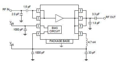
The first stage of the sub-amplifier is a complementary two-stage common emitter, denoted as Q1-7 in the circuit diagram. The common emitter configuration is widely utilized in amplifier circuits due to its ability to provide good voltage gain. In this particular circuit, the gain is approximately x2.3. This means that the output signal from this stage will be 2.3 times larger than the input signal.
Following this, the second stage of the sub-amplifier is a current mirror stage, labeled as Q13-14. A current mirror is a circuit designed to copy a current through one active device by controlling the current in another active device of a circuit, keeping the output current constant regardless of loading. The purpose of this stage in the circuit is to drive the voltage across a load resistor that is connected to 0V, also known as ground. This stage is crucial for maintaining the stability of the output signal and ensuring that it is not affected by any potential fluctuations in the input signal.
In conclusion, the circuit in question is a well-designed amplifier system that employs a two-stage amplification process to effectively increase the power of the input signal. The use of a common emitter and a current mirror stage allows for a high degree of control over the output signal, ensuring its stability and consistency.The simplified circuit [Fig.2] shows that each sub-amplifier consists of two voltage gain stages. The first stage consists of a complementary two stage common emitter [Q1-7] whose gain is about x2.3. The second stage is a current mirror stage [Q13-14] which drives the voltage across a load resistor tied to 0V.
🔗 External reference
Related Circuits
TR1 provides a constant current to a bank of three zener diodes, thus maintaining a constant voltage independent of supply voltage variations. The resistor Rx is used to sense the PSU output current and to switch off the current...
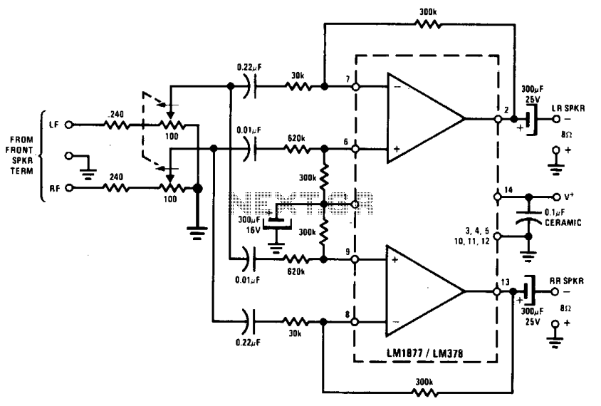
The rear channel "ambience" can be incorporated into an existing stereo system to extract a difference signal (R - L or L - R). When this signal is combined with a direct signal (R or L), it enhances the...
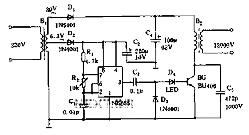
The neon voltage power supply circuit is straightforward to construct, offering stable output power and other desirable characteristics. The core component of this circuit is the NE555 timer, which generates a high-frequency oscillation signal in the range of 15...
This chapter presents a variety of circuits for basic power supplies, including both line-powered and inverter types, some of which feature regulators, modulation inputs, and additional functionalities. Several circuits have been reverse-engineered from actual commercial products, and others, designed...
Transistor amplifier circuits that are simple and easy to construct. This includes a headphone amplifier, a four-transistor amplifier, and a low-power amplifier. Transistor amplifier circuits are fundamental components in electronic design, offering various applications ranging from audio amplification to signal...
The RF2126 high-power linear amplifier IC, manufactured by RFMD, can be utilized to design a simple yet highly efficient amplifier for 2.45 GHz ISM applications, including WLAN and POS terminals. This component also serves as the final stage in...