
3-30 V/2.5 A Stabilized power supply
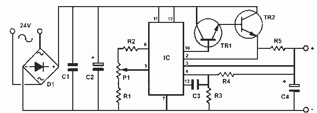
The described power supply circuit is an adjustable linear power supply capable of delivering a wide output voltage range from 3 V to 30 V with a maximum output current of 2.5 A. This flexibility makes it suitable for various applications in electronics workshops, including powering prototypes, testing circuits, and providing stable voltage levels for sensitive components.
The core of the power supply utilizes a variable resistor or potentiometer in conjunction with a voltage regulator IC, such as the LM317, which allows for continuous adjustment of the output voltage. The input voltage to the regulator should be higher than the desired output voltage, typically around 35 V to ensure proper regulation and stability.
To achieve a stable output across the entire voltage range, the circuit incorporates several key components:
1. **Voltage Regulator**: The LM317 or a similar adjustable voltage regulator is used to maintain a constant output voltage despite variations in input voltage and load current.
2. **Filtering Capacitors**: Input and output capacitors are essential for filtering out noise and providing a stable DC output. Capacitors with appropriate voltage ratings should be selected to handle the maximum input voltage.
3. **Heat Sink**: Given the potential for significant heat generation, especially at higher output currents, a heat sink is necessary to dissipate heat from the voltage regulator and maintain optimal operating temperatures.
4. **Protection Circuitry**: To safeguard against short circuits and overload conditions, the circuit may include fuses or circuit breakers, as well as current limiting features that automatically reduce output current when excessive loads are detected.
The design should also consider the layout of the circuit board to minimize resistance and inductance, which can affect performance. Proper grounding techniques and the use of twisted pair wires for connections may further enhance the stability of the output voltage.
Overall, this versatile power supply circuit is an essential tool for any electronics enthusiast or professional, providing reliable and adjustable power for a wide range of applications while ensuring safety and stability in operation.This is a very useful project for anyone working in electronics. It is a versatile power supply that will solve most of the supply problems arising in the everyday work of any electronics work shop. It covers a wide range of voltages being continuously variable from 30 V down to 3 V. The output current is 2.5 A maximum, more than enough for most applications. The circuit is completely stabilised even at the extremes of its output range and is fully protected against short-circuits and overloading.
🔗 External reference
Related Circuits
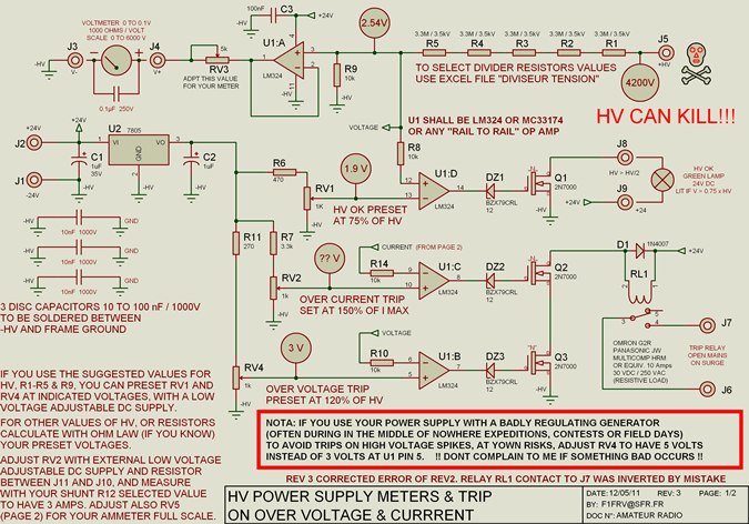
High voltage resistors for the high voltage divider are SFERNICE or PHILIPS type VR37 (3.5 kV - 0.4 W). They are not expensive (even if they are sold in quantities of 25 or 50 units), and it is always...

This circuit is designed for an LM1893 power line modem, which facilitates information transfer between remote locations using the power mains. The LM1893 serves as a power line interface for half-duplex (bi-directional) communication of serial bit streams employing various...
The circuit diagram illustrates a voltage regulator designed from discrete components to meet specific voltage requirements. It provides two sets of component values for output voltages of 6.3 V (upper) and 12.6 V (lower). The components used include BC547...
The AC power supply circuit primarily consists of a power supply, a reference voltage, a voltage comparator for sampling, and several other components. It includes a transformer for the input, an autotransformer tap for the control power supply circuit,...
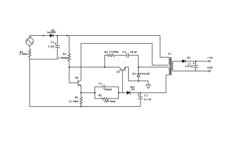
An old Nokia phone charger with a 5.6 V output was modified to provide 12 V by changing the Zener diode from a 9.1 V to a 16 V component. The circuit is mostly understood, but clarification is needed...
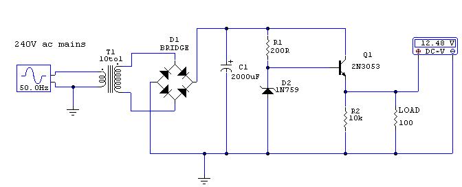
This circuit utilizes a 13-volt zener diode (D2) for voltage regulation. Approximately 0.7 volts are dropped across the base-emitter junction of the transistors, resulting in a higher current output of 12.3 volts. The circuit is capable of supplying loads...