
1.5 - 35 Volt DC Regulated Power Supply

This regulated power supply circuit is designed to convert an unregulated input voltage into a stable output voltage suitable for powering various electronic projects. The circuit typically consists of a transformer, a rectifier, a filter capacitor, and a voltage regulator.
1. **Transformer**: The transformer steps down the input AC voltage to a lower AC voltage level, which is necessary for the subsequent rectification process. The turns ratio of the transformer must be chosen based on the desired output voltage and the specifications of the project.
2. **Rectifier**: The rectifier converts the stepped-down AC voltage into pulsating DC voltage. This is usually achieved using a bridge rectifier configuration, which consists of four diodes arranged in a bridge layout. This configuration allows for full-wave rectification, improving efficiency and reducing ripple voltage.
3. **Filter Capacitor**: After rectification, the output still contains some ripple voltage. A filter capacitor is connected in parallel with the load to smooth out this ripple, providing a more stable DC voltage. The capacitance value should be selected based on the load current and the acceptable ripple voltage.
4. **Voltage Regulator**: The last stage in the circuit is the voltage regulator, which ensures that the output voltage remains constant despite variations in load current or input voltage. Common voltage regulators include the 7805 for +5V output or the LM317 for adjustable output voltages. The regulator may require additional capacitors at the input and output to maintain stability.
Overall, this regulated power supply circuit is essential for providing reliable power to various electronic devices and projects, ensuring that they operate within their specified voltage ranges. Proper selection of components and careful design considerations will enhance the performance and reliability of the power supply.The easy way to power your projects Here is the circuit diagram of regulated power supply. It is a small power supply that provides a regulated voltage, a.. 🔗 External reference
Related Circuits
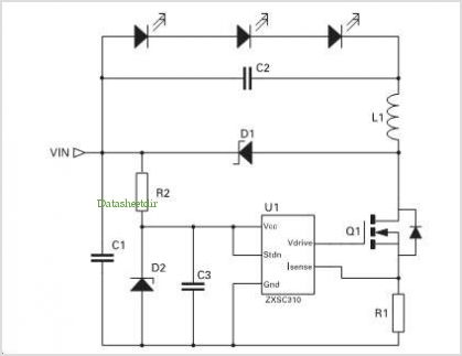
Application of the High Power LED Driver SP7652 with an Analog 0V-to-10V dimmer. Electrical Requirements: Input Voltage of 5.5V to 28V, Output Voltage VF of LED, Output Current ranging from 0 to 6A. This circuit is designed to provide...
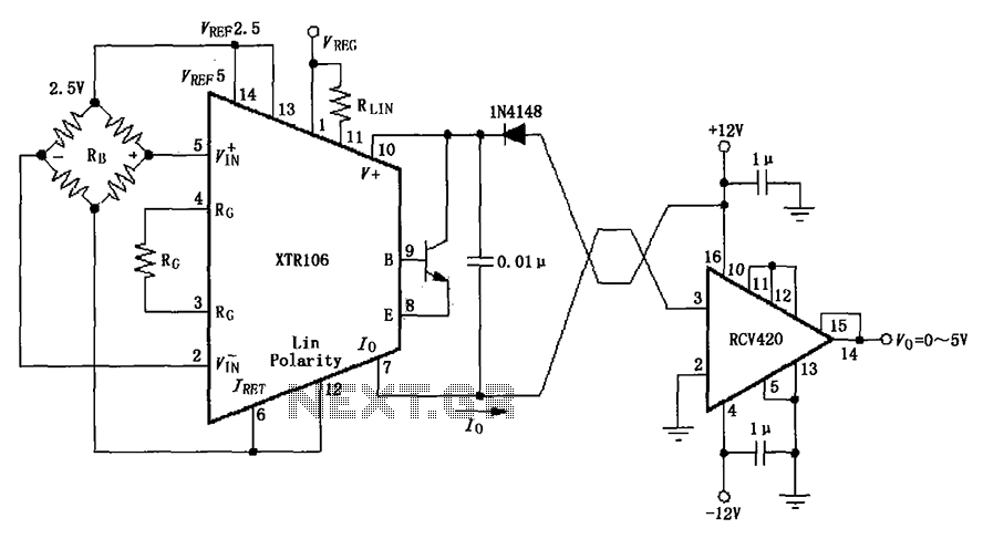
The IN4148 series diode is connected in the V+ line and configured in a loop to prevent damage from reverse voltage conditions. The diode exhibits a forward voltage drop of approximately 0.7V, which affects the supply voltage. The circuit...
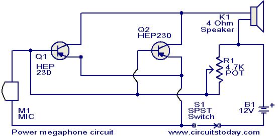
Any power transistor can be used in this megaphone, which is suitable for boats, playing fields, and similar applications. The transistors Q1 and Q2 are of the HEP-230 type, which are readily available in the market. These transistors are...
This precision power supply is a valuable addition to any workbench, serving as either a primary or supplementary power supply. It offers a voltage range of 0 to 40V and a current capacity of 2A, with adjustable current limiting...
This circuit is a simple design that outputs a voltage higher than the input. It can be used to power 12V or 9V devices from a 6V system or to operate 6V devices from a 1.5V battery. The circuit...
In this circuit, the 555 timer is utilized in an innovative manner as a voltage-controlled switch. The widely used NE555 can perform effectively in various applications. The 555 timer, a versatile integrated circuit, is commonly employed in timer, delay, pulse...