
Power Design
The electronic ballast circuit for dimming fluorescent lamps integrates a sophisticated control mechanism to provide user-friendly brightness adjustments while minimizing installation complexity. The IRS2530D DIM8 control IC at the heart of this design facilitates seamless dimming through standard on/off switches, eliminating the need for complex wiring or additional interface components.
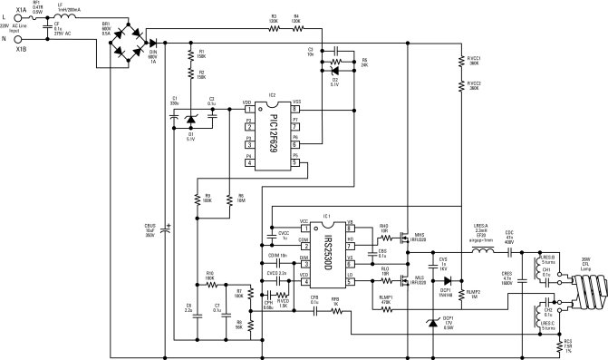
The circuit begins with the AC line input, typically sourced from either 220 Vac/50 Hz or 120 Vac/60 Hz, which is first processed through an EMI filter to suppress electromagnetic interference generated by the switching operations. Following this, the AC voltage is rectified using a full-wave rectifier, charging a smoothing capacitor to create a stable DC bus voltage. This DC voltage is then transformed into a high-frequency AC square wave by a half-bridge inverter, which is essential for driving the lamp.
The resonant tank circuit plays a critical role in both the ignition and operation of the fluorescent lamp. Initially, during pre-ignition, the circuit operates as a series-LC configuration with a high Q-factor, allowing it to efficiently generate the high-voltage required for lamp ignition. Once the lamp is lit, the circuit transitions to a series-L, parallel-RC configuration, adjusting its Q-factor based on the desired dimming level.
The control IC continuously monitors the AC line voltage cycles, enabling it to adjust the frequency of the half-bridge inverter. As the frequency decreases, the lamp filaments are preheated, leading to an increase in voltage and current until the lamp reaches its ignition threshold. After ignition, the control system maintains the lamp at the set brightness by modulating the inverter frequency, which directly influences the resonant tank's gain and thus the lamp current.
In summary, the electronic ballast circuit designed around the IRS2530D integrates advanced dimming functionality into a streamlined package, offering significant advantages in ease of installation and operational flexibility. The combination of a robust feedback mechanism and efficient power conversion ensures reliable performance across varying operational conditions, making it an effective solution for modern fluorescent lighting applications.Electronic ballasts for dimming fluorescent lamps require a control interface for the user to set the desired lamp-brightness level. Existing interface circuits include a 1-to-10-Vdc interface, digitally-addressable lighting interface (DALI), triac-based wall dimmers, three-way lamp sockets, power line communications, and wireless communications.
Each of these interface circuits requires additional wiring to each ballast during installation, a special lamp socket or wall dimmer, or an additional signal processing unit. A new circuit implemented in International Rectifier`s IRS2530D DIM8 dimming ballast control IC eliminates the need for any additional interface components by sensing the on/off switching of the ac line voltage and cycling through the dimming range in four steps.
This allows for the lamp to be dimmed with any standard on/off switch without any additional wiring. The IRS2530D provides all of the necessary ballast functions, fault detection and dimming control required for operation of fluorescent lamps. A microcontroller and pulse detection circuit is used to sense each recycling of the ac line voltage, change the dimming reference, and store the previous dimming level.
This article explains how the IRS2530D operates and presents a complete four-level switch-dimming application circuit built around this IC. A complete set of schematics and waveforms is included to help designers better understand and design the new circuit.
The electronic ballast circuit block diagram (Figure 1) includes the ac line input voltage (typically 220 Vac/50 Hz or 120 Vac/60 Hz), an EMI filter to block circuit-generated switching noise, a rectifier and smoothing capacitor, a control IC and half-bridge inverter for dc-ac conversion, and the resonant tank circuit to ignite and run the lamp. The additional circuit block required for dimming is also shown. This circuitry includes a dimming reference signal, a lamp-current sensing and feedback signal, and a summing circuit for closed-loop control of the lamp current.
The lamp requires a current to preheat the filaments, a high-voltage signal for ignition, and a high-frequency ac current to maintain operation during the running mode. To fulfill these requirements, the electronic ballast circuit first performs a low-frequency ac-dc conversion at the input, followed by a high-frequency dc-ac conversion at the output.
First, the ac line voltage is full-wave rectified with the output of rectifier peak-charging a capacitor to produce a smooth dc bus voltage. The dc bus voltage is then converted into a high-frequency, 50% duty-cycle, ac square-wave voltage using a standard half-bridge switching circuit.
The high-frequency ac square-wave voltage then drives the resonant tank circuit and becomes filtered to produce a sinusoidal current and voltage at the lamp. During pre-ignition, the resonant tank is a series-LC circuit with a high Q-factor. After ignition and during the running mode, the tank is a series-L, parallel-RC circuit with a Q-factor somewhere between a high and low value depending on the lamp dimming level.
When the CFL is first turned on, the control IC sweeps the half-bridge frequency from the maximum frequency down towards the resonance frequency of the high-Q ballast output stage. The lamp filaments are preheated as the frequency decreases and the lamp voltage and load current increase (Figure 2).
The frequency keeps decreasing until the lamp voltage exceeds the lamp ignition voltage threshold and the lamp ignites. Once the lamp ignites, the lamp current is controlled such that the lamp runs at the desired power and brightness level.
To dim the fluorescent lamp, the frequency of the half-bridge is increased, causing the gain of the resonant tank circuit to decrease and therefore the lamp current to decrease. A closed-loop feedback circuit is then used to measure the lamp current and regulate the current to the dimming ref
🔗 External reference
Related Circuits
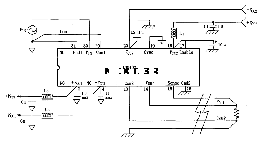
The basic connection circuit for the ISO107 signal and power supply is illustrated. Each power supply terminal must include a bypass filter. If the output current from the isolated power supply exceeds 15 mA, it is advisable to utilize...
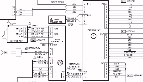
The AVANT employs a Switched Mode Power Supply (SMPS), which is centered around a 32 kHz ramp oscillator. This oscillator ceases operation if the overload protection circuit identifies an overload condition. When the oscillator is inactive, the 8-volt standby...
Flyback LED drivers are versatile as they can be utilized in applications with input voltages either above or below the necessary output voltages. They feature a straightforward circuit configuration that maintains a constant LED current without the need for...
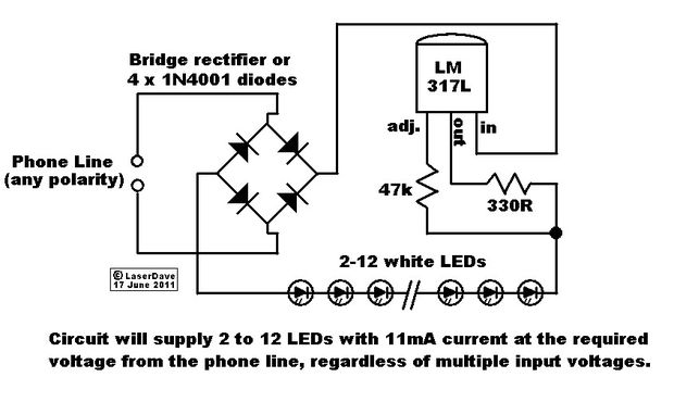
This circuit operates in a manner that allows the phone line to remain active while the LEDs are connected. When the phone is picked up, the light turns off, enabling normal phone usage. The phone line delivers 48V DC...
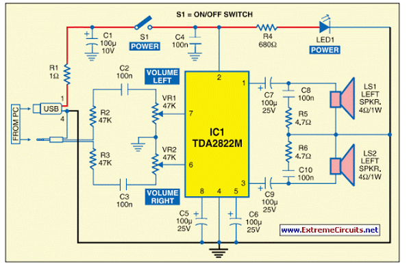
This circuit of multimedia speakers for PCs features a single-chip design, operates on a low-voltage power supply, is compatible with USB power, and allows for easy heat dissipation. The multimedia speaker circuit is designed to enhance audio output for personal...
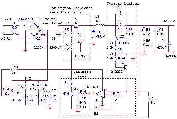
The switching power supply, shown in the schematic, provides 12 volts, at 10 amps, maximum, using a discrete transistor regulator with an op-amp functioning as a comparator in the feedback circuit. The supply was constructed in 1984 and is...