
LTC1042 wind charger circuit schematic project

The wind charger circuit primarily employs the LTC1042, which serves as a window comparator to monitor the voltage levels of the generator output. The circuit is designed to operate within specific voltage thresholds to ensure safe and efficient charging of the batteries. The LTC1042 compares the generator voltage against preset reference levels, activating the charging process when the voltage is sufficiently low and disengaging it when the voltage rises too high.
The LM334 current source plays a crucial role in regulating the charging current to the Ni-Cd battery, ensuring that it receives an appropriate amount of charge without exceeding safe limits. This is particularly important for maintaining the longevity and performance of the battery. The circuit's design effectively prevents overcharging, which can lead to battery damage or reduced lifespan.
In scenarios where the generator voltage exceeds the upper threshold of 15.1V, the circuit automatically connects a fixed load. This load serves to dissipate excess energy generated by the wind turbine, thereby controlling the RPM of the generator. By limiting the RPM, the circuit mitigates the risk of mechanical failure or damage to the generator components, which could occur under excessive wind conditions.
Overall, this wind charger circuit is an efficient solution for harnessing wind energy to charge batteries, providing a sustainable power source while incorporating safety features to protect both the generator and the batteries involved. The careful selection of components and the design of the control mechanisms ensure reliable operation in varying wind conditions.This simple wind Charger circuit electronic project is designed using the LTC1042 monolithic CMOS window comparator, manufactured by Linear Technology. This Wind charger circuit electronic project use the wind power to produce the energy required to charge Ni-Cd or Lead Acid batteries.
If generator voltage output is below 13. 8V, the control circ uit is active and the NiCad battery is charging through the LM334 current source (the lead acid battery is not being charged). If generator voltage exceeds 15. 1V (a condition caused by excessive wind speed or 12V battery being fully charged) then a fixed load is connected thus limiting the generator RPM to prevent damage.
🔗 External reference
Related Circuits
The figure illustrates an NE555 frequency modulation (FM) circuit. In this circuit, pin 7 of the NE555 is connected to an FM modulation section that consists of resistor R5 and capacitor C2, although the frequency range is somewhat limited....
GND and VCC are positioned perpendicularly to the other pins in the circuit diagrams, while the actual Z80 is a DIP with no pins in these locations. This arrangement complicates the readability of the circuit diagram, necessitating a mapping...
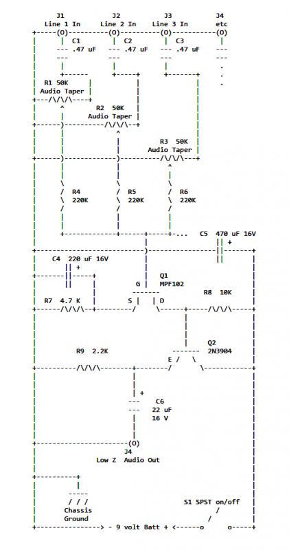
If two of these circuits are made in the same enclosure for stereo, then there can be a single power supply to run both of them. There should be a resistor in series with the incoming 9V+ lead so...
The following circuit illustrates an Elektroblock circuit diagram utilizing a 12V power supply. Features include various control and monitoring functions, with the specification of an 18 A LAS 1218 component. The Elektroblock circuit is designed to operate with a 12V...
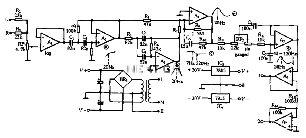
This electronic bass equalizer circuit utilizes two quad operational amplifiers, specifically the TL084 high-speed operational amplifier. The circuit includes left and right channels that are mixed through resistors R1 and R2, and features a total bass level adjustment potentiometer...
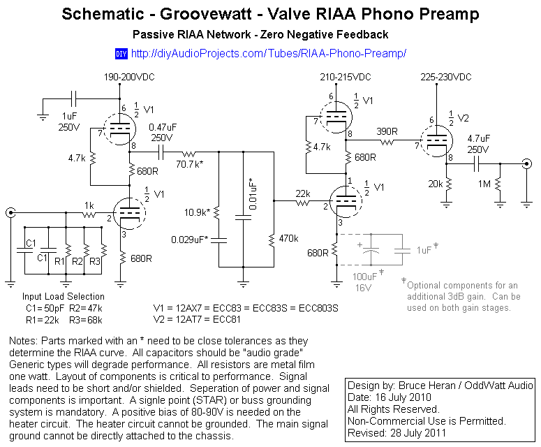
This project has been in development for over a year, initially postponed due to concerns about design complexity and the availability of high-quality phono preamps. The objective was to create a preamp that would deliver performance comparable to commercial...