Power Flashers
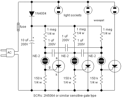
A simple circuit for sequentially flashing Christmas light strings or other similar low-power lamps. The socket symbols may represent single bulbs or sockets for lamp strings. The load must operate from DC since the SCRs rectify the line voltage. The SCRs should be sensitive-gate types capable of handling the load current and line voltage. The 1uF capacitors are non-polar film types. A fuse is indicated, and a GFI type outlet is recommended. Warning: This circuit should only be constructed by individuals qualified to work on and design high-voltage circuitry. Necessary safety considerations are not indicated. All parts of the circuit should be considered "hot." The circuit can be extended by repeating the pattern, connecting the last neon lamp back to the first through a capacitor. Although a quick breadboard was tested, this circuit is "experimental" and may require some adjustments for optimal performance. The flashing speed can be controlled by connecting a 100k ohm (or larger) potentiometer across the 10uF capacitor and connecting the 1 megohm resistors to the wiper. It is important to ensure that the potentiometer shaft is insulated. The 1 megohm resistors may be reduced in value for faster flashing. This circuit is an unusual flasher circuit for 120VAC loads, similar to the two-transistor flasher seen in various circuits except that an SCR is used. Warning: This circuit should only be constructed by individuals qualified to work on and design high-voltage circuitry. Necessary safety considerations are not indicated. All parts of the circuit should be considered "hot." A notable feature is the selection of the 0.1uF capacitor in series with the 1k resistor. When the SCR is off, this capacitor smooths the ripple from the bridge sufficiently for the transistor flasher circuitry to function properly. However, when the SCR turns on, the capacitor discharges immediately and will not provide enough current to keep the SCR on. Additionally, the capacity is low enough to retain a significant amount of ripple voltage, causing the circuit to trigger near zero volts, which is a desirable feature. The power handling device is a sensitive-gate SCR rated for at least 200 volts and with a current rating sufficient to manage the expected load. Sensitive-gate SCRs typically have a gate trigger current around 200uA. The PNP transistor can be any general-purpose type, or a high-voltage type may be selected to minimize the risk of damage during experimentation. The transistor typically operates at about 35 volts. Necessary fuses and line filtering are not shown. A power input module with all components built in is highly efficient. Low power loads will not generate significant line noise, but a fuse is always recommended. When power is initially applied, the SCR remains off, and the 0.1uF capacitor charges to approximately 160 volts with some ripple. The base voltage experiences a divided-down version of this rippling voltage, approximately 35 volts. The 22uF capacitor begins charging through the 1 megohm resistor, and the emitter voltage rises toward the base voltage. When the capacitor voltage reaches around 35 volts and exceeds the base voltage (typically a low point in the ripple voltage), the transistor conducts, triggering the SCR. This triggering lowers the voltage on the base, and the transistor turns on strongly due to the higher voltage on the emitter. The transistor remains on until the capacitor discharges to a level where the gate current cannot keep the SCR triggered. The SCR turns off at the next voltage zero-crossing, and the process repeats. The circuit tends to activate and deactivate near zero-crossings. The 1k resistor in series with the 0.1uF capacitor protects the SCR from high discharge currents, although most SCRs can handle the current surge without this resistor. The 1 megohm resistor connected to the 22uF capacitor can be adjusted to change the flash rate.A simple circuit for sequentially flashing Christmas light strings or other similar low-power lamps. The socket symbols may be single bulbs or sockets for lamp strings. The load must be capable of operating from DC since the SCRs rectify the line voltage. The SCRs must be sensitive-gate types and must be able to handle the load current and line voltage. The 1uF capacitors are non-polar film types. A fuse is indicated and a GFI type of outlet is recommended. Warning: This circuit should be constructed only by persons with the qualifications to work on and design high voltage circuitry. Necessary safety considerations are not indicated. All parts of the circuit should be considered "hot". The circuit may be extended by repeating the pattern with the last neon lamp connecting back to the first through a capacitor.
Although a quick breadboard was tested, this circuit is "experimental" and may require some tweaking for best performance. The flashing speed may be controlled by connecting a 100k ohm (or larger) potentiometer across the 10 uF capacitor and connecting the 1 meg resistors to the wiper.
Make sure that the shaft is an insulated type. The 1 meg resistors may be lowered in value for faster flashing. Here is an unusual flasher circuit for 120VAC loads. The circuit is similar to the two-transistor flasher seen in several circuits in techlib. com except that an SCR is used. Warning: This circuit should be constructed only by persons with the qualifications to work on and design high voltage circuitry. Necessary safety considerations are not indicated. All parts of the circuit should be considered "hot". A little circuit trick is hiding in the selection of the 0. 1uF capacitor in series with the 1k resistor. When the SCR is off, this capacitor smoothes the ripple from the bridge sufficiently for the transistor flasher circuitry to work properly but when the SCR turns on, the capacitor immediately discharges and will not provide enough current to keep the SCR on.
Also, the capacity is low enough to leave quite a bit of ripple voltage causing the circuit to trigger near zero volts - a desirable feature! The power handling device is a sensitive-gate SCR with a rated voltage of at least 200 volts and with a current rating sufficient to handle the expected load.
Sensitive-gate SCRs typically have a gate trigger current near 200uA. The PNP transistor may be just about any general-purpose type or a high voltage type may be selected to reduce the chances of zapping it while experimenting! Ordinarily, the transistor sees about 35 volts. Not shown are necessary fuses and line filtering. A power input module with everything built in is hard to beat. Low power loads will not generate much line noise but a fuse is always recommended. When power is first applied, the SCR is off and the 0. 1uF capacitor charges to about 160 volts with several volts of ripple. The base voltage sees a divided-down version of this rippling voltage, near 35 volts. The 22uF capacitor begins charging through the 1meg resistor and the emitter voltage begins to rise towards the base voltage.
When the capacitor voltage reaches about 35 volts and exceeds the base voltage (typically a low point in the ripple voltage), the transistor conducts causing the SCR to trigger. The triggering pulls the voltage on the base low and the transistor turns on hard because of the now-higher voltage on the emitter.
The transistor stays on until the capacitor is discharged to the point that the gate current cannot keep the SCR triggered. The SCR turns off at the next voltage zero-crossing and the process repeats. Notice how the circuit tends to turn on and off near zero-crossings! The 1k in series with the 0. 1uF capacitor protects the SCR from high discharge currents. (Most SCRs can handle the current surge without the resistor. ) The 1meg resistor connected to the 22uF may be varied to change the flash rate or the 🔗 External reference
