
Remote Control Mains Switch
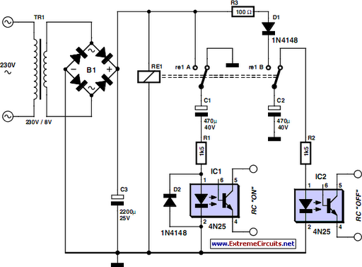
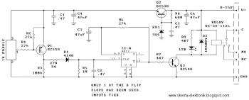
The operation is as follows: when the lady pulls the cord or operates the switch, mains voltage is applied to the transformer, activating the relay and charging capacitor C1. While C1 is charging, a small current flows through optocoupler 1, simulating a press of the "on" button on the remote control. This action activates the corresponding power point to which the standing lamp is connected, turning it on. Simultaneously, capacitor C2 charges. If the lady pulls the cord again or operates the switch, the relay de-energizes, causing C2 to discharge through optocoupler 2, which activates the "off" contact of the remote control and turns off the light. The remote control continues to operate from its normal battery, and the white enclosure is mounted to the ceiling in place of the light fitting. Diode D1 ensures that C1 discharges when the relay de-energizes, while D2 prevents C2 from discharging through the relay, allowing it to discharge only through optocoupler 2.
This circuit utilizes a 4N25 opto-coupler to isolate the low-voltage control circuit from the high-voltage mains circuit, ensuring safety and efficiency. The relay acts as a switch that is controlled by the light switch or pull cord, effectively transforming the existing light control into a mechanism that operates the standing lamp. The use of capacitors C1 and C2 allows for a delay in the operation of the remote control, providing a reliable response to the lady's actions. The integration of diodes D1 and D2 adds an extra layer of protection, ensuring that the circuit functions correctly without unintended discharges. Overall, this solution offers a practical and user-friendly means for the elderly lady to control her standing lamp with ease and comfort.As the only electronics engineer in my family and circle of friends, it is sometimes not possible to evade an appeal for help. This time the request came from a friendly elderly lady in a retirement home. In her room the light switch by the door and the pull cord above the bed operate the light fitting on the ceiling in the middle of the room.
How ever, she would prefer that her standing lamp was operated by these switches instead, since she does not actually have a light fitting mounted on the ceiling. This standing lamp has an on/off switch in the power cord and is plugged into a power point. However, it stands rather far from the bed so that she always has to find her way in the dark. A wireless operated power point is not really a consideration, because it is just a matter of time before the remote is lost.
Or maybe not Behold a feasible circuit. Buy a wireless power point and an enclosure that is big enough for the remote control and a small piece of prototyping board. On the proto-typing board build the circuit according to the accompanying schematic and (carefully) open the remote control and solder wires to the push buttons for on` and off`.
Measure if these are polarised and if that is the case connect them to the 4N25 opto-couplers as shown in the schematic, where pin 5 has a higher voltage than pin 4. The operation is as follows. The lady operates the pull cord or light switch to turn the light on. This causes the mains voltage to be applied to the transformer. The relay is activated which charges C1. While C1 charges, a small current flows through optocoupler 1. The result is that the on` button on the remote control is pressed. The remote control switches the corresponding power point on and to which the standing lamp is connected.
The standing lamp will therefore now turn on. Capacitor C2 is charged at the same time. If the lady pulls the cord again, or if she operates the switch near the door, the relay will de-energize and C2 discharges across optocoupler #2. This operates the off` contact of the remote control and the light goes out. The remote control continuous to operate from its normal battery and the white enclosure is attached to the ceiling in place of the light fitting.
Diode D1 ensures that C1 is discharged when the relay de-energises. D2 ensures that C2 cannot discharge across the relay, but only across optocoupler 2. 🔗 External reference
Related Circuits
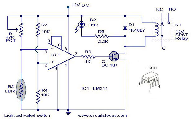
The following circuit illustrates a Light Activated Switch Circuit Diagram. This circuit is based on the LM311 integrated circuit, which functions as a voltage comparator. The Light Activated Switch Circuit utilizes the LM311 voltage comparator to control the switching of...
This circuit illustrates a lighting control circuit diagram with a power rating of approximately 300-350W. Features include low cost, simplicity, and operation at 120V AC voltages. Components: .. The lighting control circuit designed for 300-350W applications is intended to provide...
This circuit utilizes a controlled half-plus fixed half-wave phase control method to regulate an 860-watt lamp load, allowing for power adjustment from half to full capacity. The circuit controls the light output of the lamp, enabling a range from...
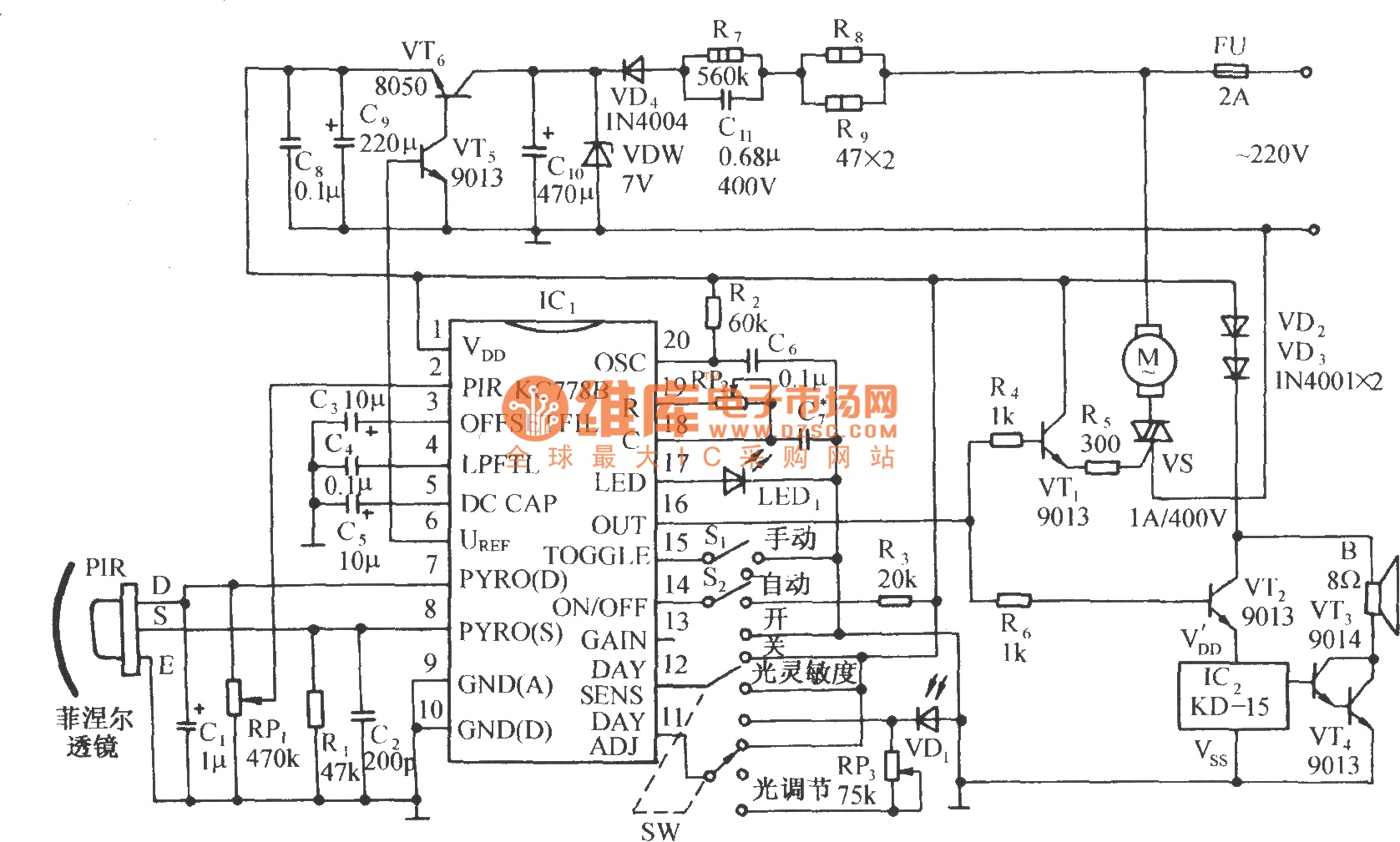
The circuit is depicted in the diagram. It is a control circuit that consists of the infrared-specific integrated circuit KC778B, which serves as the central component. Surrounding it are a pyroelectric infrared sensor head (PIR), a light control and...
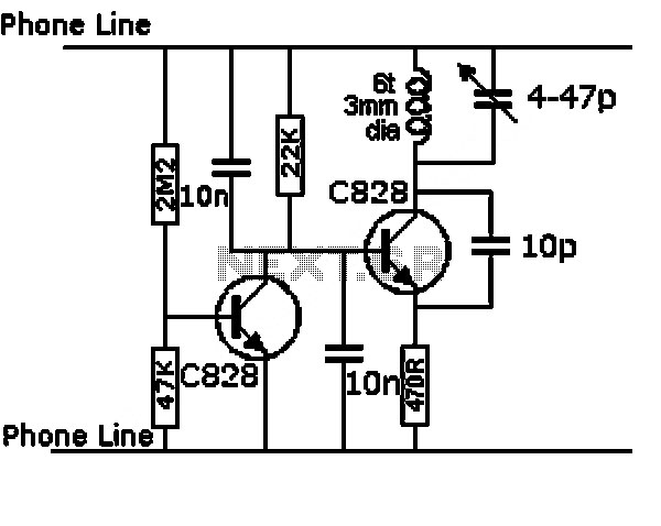
All modern infrared (IR) remote control devices generate a continuous coded stream of pulses at 37.9 kHz when any button on the device is pressed. These IR pulses are received and decoded by a compatible device, such as a...
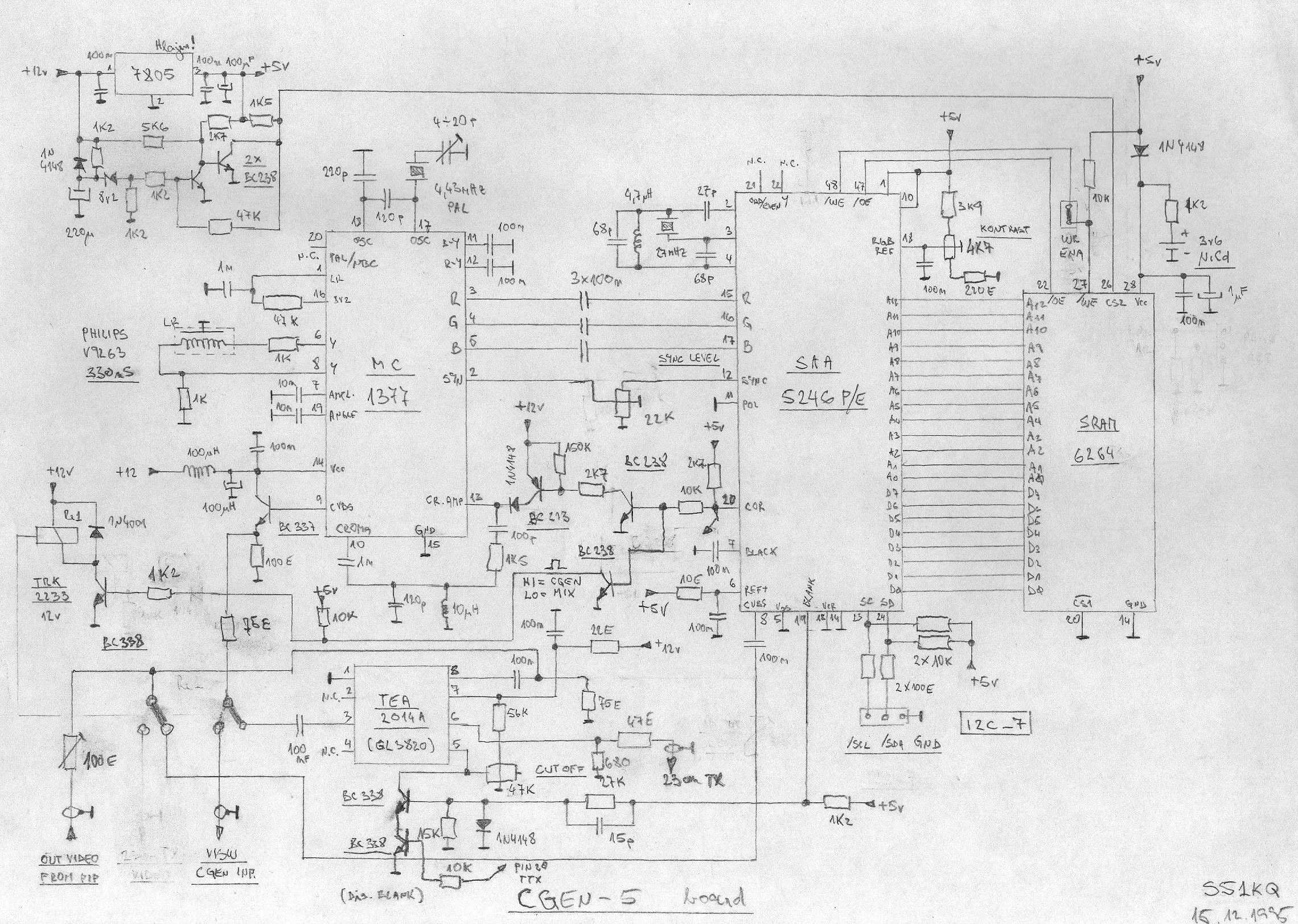
This is an image Schematic. No Description available. The provided input indicates that there is an image schematic without any accompanying description. In scenarios where a schematic is presented, it typically contains graphical representations of electronic components and their...