
Power-line outage flashes red alert
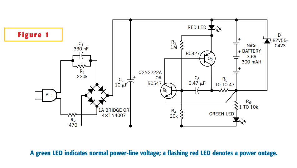
The described circuit functions as a power-outage detector that utilizes a combination of components to monitor line voltage and activate an alarm during a power failure. The circuit is designed to be plugged directly into a mains outlet, where it can continuously monitor the voltage level.
The primary component responsible for indicating the presence of line voltage is the green LED. When the mains power is present, the LED illuminates, providing a visual indication that the circuit is operational. This LED is connected in such a way that it receives its bias voltage from a resistor labeled R6, which ensures that the LED operates within its specified current limits.
To protect the battery system from potential overvoltage conditions, a BZV55-C4V3 zener diode (D1) is employed. This diode clamps the voltage at a predetermined level, ensuring that the trickle-charged nickel-cadmium batteries do not exceed their maximum voltage rating. This is crucial for maintaining battery health and longevity, as overcharging can lead to reduced performance or failure.
The circuit employs a bipolar junction transistor (BJT), Q1, which is kept in the off state during normal operation due to the biasing provided by R6 and the green LED. This configuration prevents the Q1-Q2 RC oscillator from activating, meaning that the alarm remains silent when power is supplied. However, in the event of a power outage, the absence of line voltage causes the green LED to turn off, which in turn allows Q1 to turn on. This transition triggers the RC oscillator circuit formed by Q1 and Q2, resulting in an audible alarm that alerts users to the power failure.
Overall, this design effectively combines visual and auditory signals to notify users of power interruptions, while also incorporating protective measures for the battery system. The simplicity of the circuit design allows for easy implementation and reliable operation in various applications where power outage detection is critical.This Design Idea expands on a circuit in a previous one to configure a power-outage detector with a flashing alarm (Figure 1, Reference 1). The circuit plugs into a mains outlet and uses trickle-charged nickel-cadmium batteries. The green-LED monitors the presence of line voltage. The BZV55-C4V3 zener diode, D1 protects the batteries against overvoltage. Voltage bias from R6 and the green LED keeps Q1 off, so the Q1-Q2 RC oscillator remains off. 🔗 External reference
Related Circuits

The transmitter keyboard is organized as a scanned matrix consisting of 7 driver outputs and 7 sense inputs. The driver outputs, labeled DRVON to DRV6N, are open-drain n-channel transistors that remain conductive in standby mode. The 7 sense inputs,...

A simple device that enables a quick check of common infrared remote controls can be beneficial for electronics enthusiasts often tasked with repairing or testing these widely used devices. A dependable circuit has been designed using a few components:...

An array of white LEDs can serve as a small lamp for the living room. LED lamps are readily available, resembling standard halogen lamps, and can be installed in a standard 230-V light fixture. A capacitor is employed to...

The circuit consists of the following components: (1) An infrared emitter which utilizes a multi-harmonic oscillator based on a 555 timer circuit. The oscillation frequency is determined by the values of RP1, R1, and C1, resulting in a frequency...
The circuit for the solar-powered controller includes a switching circuit, a pulsing circuit, and a high-voltage output circuit. The external power components consist of a 1- to 5-W solar panel and a 12-V motorcycle or camcorder battery. The output...
This is a straightforward infrared detector circuit designed to detect infrared light. The circuit comprises only three components: an RS-276-145 photo transistor, a 330-ohm resistor, and a general-purpose LED (Light Emitting Diode). When the photo transistor receives infrared light...
Warning: include(partials/cookie-banner.php): Failed to open stream: Permission denied in /var/www/html/nextgr/view-circuit.php on line 713
Warning: include(): Failed opening 'partials/cookie-banner.php' for inclusion (include_path='.:/usr/share/php') in /var/www/html/nextgr/view-circuit.php on line 713