
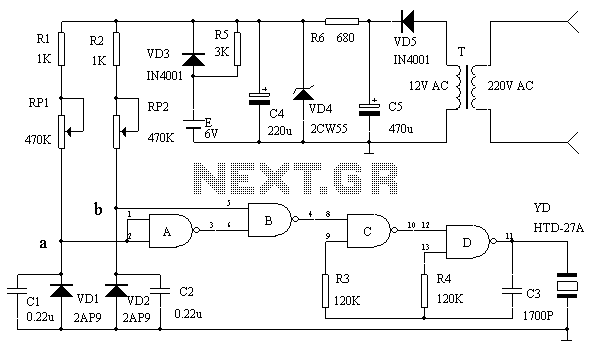
Infrared automatic faucet circuit diagram
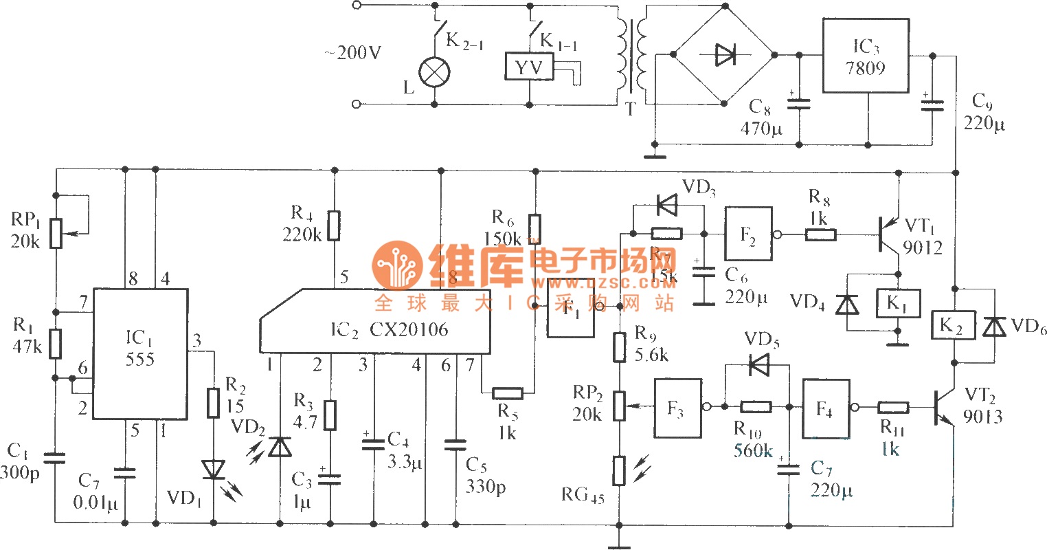
The circuit operates as a comprehensive control system for various applications. The infrared emitter generates a modulated infrared signal at a frequency of 38 kHz, which is optimal for many infrared communication applications, ensuring minimal interference from ambient light sources. The 555 timer is configured in astable mode, with the oscillation frequency being adjustable through the resistors and capacitor connected to it.
The infrared receiver circuit is designed to detect the emitted signal. The infrared receiver tube (VD2) captures the infrared light, while the CX20106 serves as a demodulator, processing the received signal to trigger subsequent actions in the circuit.
The water valve control circuit allows for automation of water flow using controlled gates (F1 and F2) to manage the opening and closing of the valve. The drive tube (VT1) amplifies the control signal, while relay (K1) acts as a switch to physically control the water valve.
Similarly, the lamp control circuit operates in a parallel fashion, where control gates (F3 and F4) manage the operation of a lamp. The drive tube (VT2) amplifies the control signal for the relay (K2), enabling or disabling the lamp based on the received infrared signal.
This circuit design demonstrates versatility in controlling multiple devices using infrared communication, making it suitable for remote control applications in various electronic systems.The circuit is composed of the parts below: (1) infrared emitterThe multi-harmonic oscillator is comoposed of 555 circuit. The oscillation frequency is decided by value of the RP1, R1, C1. The circuit`s oscillation frequency is 38kHz. (2) infrared receiver circuitThe circuit is composed of infrared receiver tube VD2 and CX20106. (3) water valve con trol circuitThe circuit is composed of controlled gate F1, F2 and drive tube VT1 and relay K1. (4) lamp control circuitThe circuit is composed of the control gate F3, F4, drive tube VT2 and relay K2. 🔗 External reference
Related Circuits
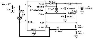
The ADM666A application note provides a detailed explanation of a low-cost battery charger circuit, including maximum output voltage, charge termination voltage calculation, battery voltage level monitoring, and circuit efficiency optimization. The ADM666A utilizes an NPN transistor and a P-channel...
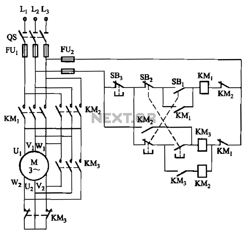
A hoist rated at 22kW and below is equipped with a power-saving Y-conversion circuit, as depicted in the figure. This circuit enhances the standard hoist design by incorporating a CJ20-10A exchange contactor. The implementation of the Y-conversion circuit during...
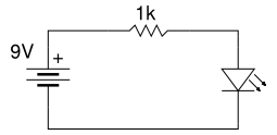
Beginner's Tutorial 1: Building a Circuit on Breadboard - how to build a simple and easy circuit on a breadboard for beginners in electronics. Learn to use an LED and a resistor. This tutorial serves as an introductory guide for...
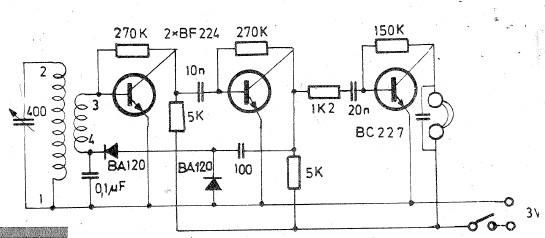
Oscillating circuits (coils) are constructed on a ferrite bar. For long wave reception, winding "1-2" consists of 135 turns, while winding "3-4" consists of 20 turns. For medium wave reception, winding "1-2" has 75 turns, and winding "3-4" has...
This circuit serves as an over-temperature alarm and cooling system utilizing CD4011 four NAND gate integrated circuits to monitor the oven's temperature. In the event of a thermostat circuit failure or power outage, if the internal temperature exceeds or...
An efficient 4-stage stabilized power supply unit is designed for testing electronic circuits. This unit provides well-regulated and stabilized output, which is essential for most electronic circuits to yield accurate results. The circuit features audio-visual indicators to signal a...