
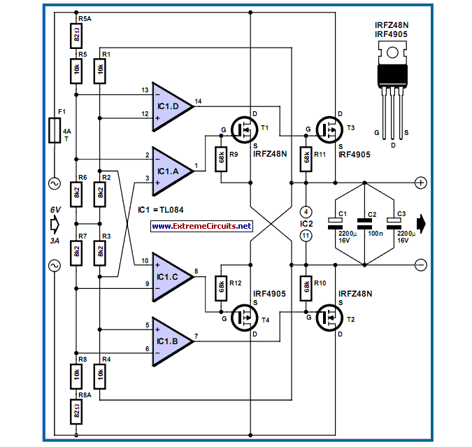
Power MOSFET Bridge Rectifier
In a bridge rectifier circuit, the configuration consists of four diodes arranged in a bridge formation, allowing for the conversion of alternating current (AC) to direct current (DC). The primary advantage of this topology is that it enables full-wave rectification, utilizing both halves of the AC waveform, which results in a smoother output voltage compared to half-wave rectification.
When low voltages are rectified, the forward voltage drop across the diodes becomes a crucial factor. Typically, silicon diodes exhibit a forward voltage drop of about 0.7 V per diode. In a bridge rectifier, two diodes conduct during each half-cycle of the AC input, leading to a cumulative voltage drop of approximately 1.4 V. This drop can be significant, especially when the input voltage is low, as it reduces the effective output voltage available for the load.
To mitigate the impact of these losses, alternative diode technologies such as Schottky diodes, which possess a lower forward voltage drop (approximately 0.3 V), can be employed. This substitution can enhance the efficiency of the rectifier, particularly in low-voltage applications where every millivolt matters.
Additionally, it is essential to consider heat dissipation in the design, as the power loss due to the forward voltage drop translates into heat, which can affect the reliability and longevity of the components. Proper thermal management strategies, such as heat sinks or active cooling, may be necessary to maintain optimal operating conditions.
In summary, while bridge rectifiers are effective for converting AC to DC, careful consideration must be given to the voltage drop across the diodes, especially in low-voltage scenarios, to ensure efficient operation and to minimize losses.The losses in a bridge rectifier can easily become significant when low voltages are being rectified. The voltage drop across the bridge is a good 1.5 V,.. 🔗 External reference
Related Circuits
This is a 2x60W LM4780 Power Amplifier. The LM3886 was initially considered for this project due to its acclaim in previous designs. However, feedback suggested a need for a complete device. The LM3886 integrated circuit was difficult to source,...
This is a low-power voltmeter circuit suitable for alternative energy systems operating on 12-volt and 24-volt batteries. The voltmeter features an expanded scale design, allowing it to display small voltage increments within the 10 to 16-volt range for 12-volt...
The MAX34446 data logger for power supplies is capable of monitoring voltages for overvoltage and undervoltage conditions, as well as overcurrent and overtemperature situations. The device continuously checks user-programmable thresholds. The MAX34446 is an advanced monitoring solution designed for power...
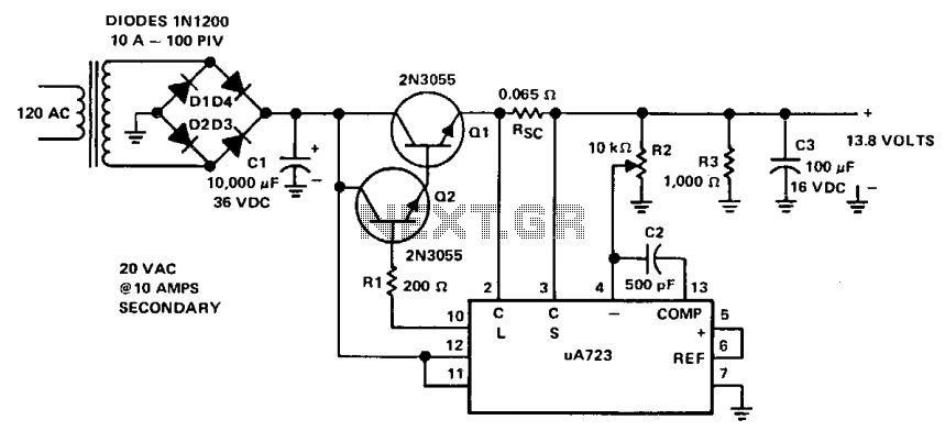
This power supply is powered by a transformer that operates from 120 Vac on the primary side and provides approximately 20 Vac on the secondary side. A full-wave bridge rectifier is constructed using four 10-A diodes rated at 100...
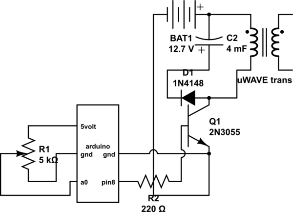
If both devices need to be powered from the battery, should the emitter be connected to the ground of the Arduino and the battery to prevent current from flowing through the Arduino ground, ensuring a clean pulse? Alternatively, can...
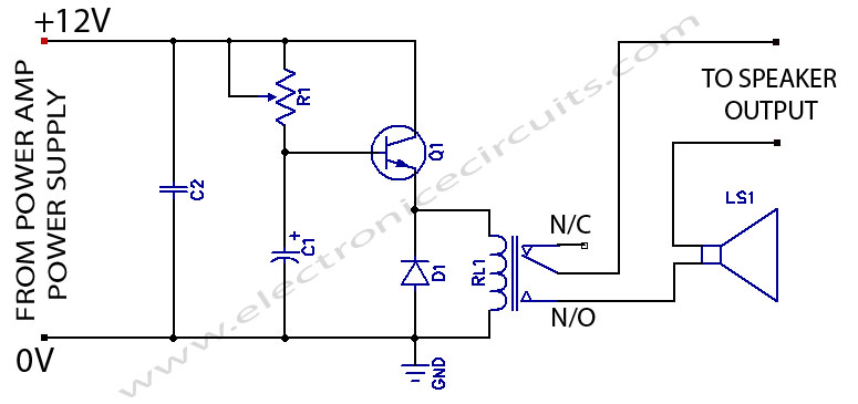
When powering on a power amplifier, a loud thump sound occurs due to a sudden heavy discharge current through the speaker. This current has the potential to damage the speaker, particularly in the case of a direct-coupled amplifier. The phenomenon...