
8-Amp regulated power supply
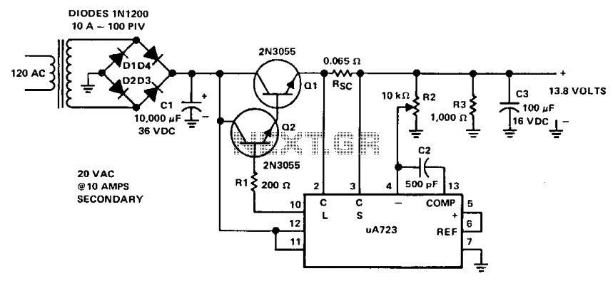
This power supply design utilizes a transformer with a primary voltage of 120 Vac to step down to approximately 20 Vac on the secondary side. The full-wave bridge rectifier configuration, consisting of four diodes with a current rating of 10 A and a peak inverse voltage (PIV) of 100 V, ensures efficient rectification of the AC voltage into DC. The significant capacitance of 10,000 µF at 36 Vdc serves to smooth the rectified output, yielding a stable 28 Vdc.
The output voltage is regulated using a Darlington pair configuration with 2N3055 transistors, known for their high current gain, allowing for efficient power regulation. The µ723 voltage regulator plays a crucial role in controlling the output voltage. It provides a reference voltage of 7.15 V to the error amplifier, which compares this reference against the feedback voltage derived from the output. The 10 k ohm potentiometer allows for fine-tuning of the output voltage, which is set to 13.8 V, making it suitable for various applications requiring a stable supply.
The use of a 500 pF capacitor for compensation ensures the stability of the error amplifier by preventing oscillations, thereby maintaining reliable operation under varying load conditions. Additionally, the design incorporates protective features; should the load current exceed 8 A or a short circuit occur, the µ723 regulator will deactivate the output transistors, effectively dropping the output voltage to prevent damage to the circuit components. This ensures that the power supply can safely handle overload conditions while maintaining the integrity of the overall system.This supply is powered by a transformer operating from 120 Vac on the primary and providing approximately 20 Vac on the primary, and providing approximately 20 Vac on the secondary. Four 10-A diodes with a 100 PIV rating are used in a full-wave bridge rectifier. A 10,000 ^F/36 Vdc capacitor completes the filtering, providing 28 Vdc. The dc voltage is fed to the collectors of the Darlington connected 2N3055's. Base drive for the pass transistors is from pin 10 of the µ723 through a 200 ohm current limiting resistor, Rl.
The reference terminal (pin 6) is tied directly to the non-inverting input of the error amplifier (pin 5), providing 7.15 V for comparison. The inverting input to the error amplifier (pin 4) is fed from the center arm of a 10 k ohm potentiometer connected across the output of the supply. This control is set for the desired output voltage of 13.8 V. Compensation of the error amplifier is accomplished with a 500 pF capacitor connected from pin 13 to pin 4.
If the power supply should exceed 8 A or develop a short circuit, the µ723 regulator will bias the transistors to cutoff and the output voltage will drop to near zero until the short circuit condition is corrected. 🔗 External reference
Related Circuits
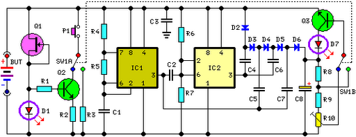
This circuit performs a rapid battery test without requiring a power supply or costly moving-coil voltmeters. It offers two testing ranges: when switch SW1 is positioned as indicated in the circuit diagram, the device can test batteries ranging from...
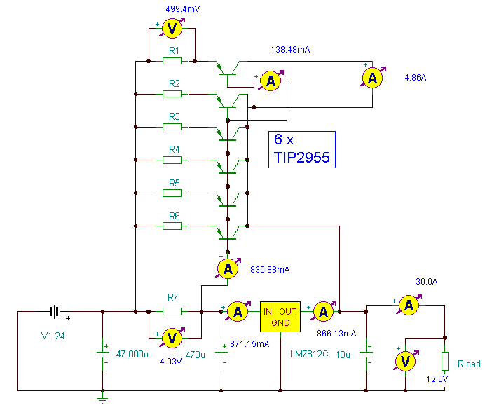
This power supply utilizes a single 7812 integrated circuit (IC) voltage regulator in conjunction with multiple external pass transistors to provide output load currents of up to 30 amps. The circuit design incorporates a 7812 voltage regulator, which is known...
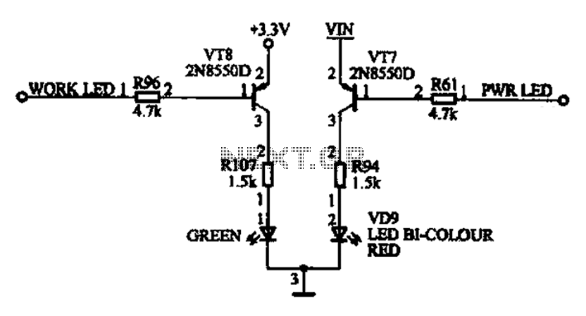
The ACER PM02 MP4 machine features a voltage status indicator circuit. When power is supplied, a red LED illuminates, indicating that the device is powered on. Upon entering operational mode, a green LED lights up. The voltage status indicator circuit...
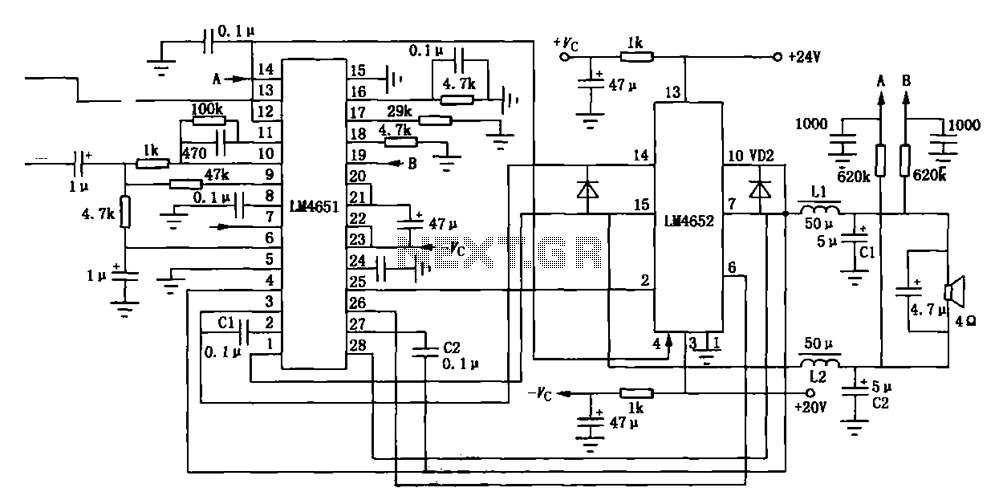
Figure (a) illustrates a 170W output amplifier circuit designed for a 4-ohm load. The LM4651 is a class D amplifier presented in a 28-pin DIP package, with its internal equivalent circuit depicted in Figure (c). The 170W output amplifier circuit...
The NCP1072/NCP1075 products integrate a fixed frequency current mode controller with a 700 V MOSFET. Available in a PDIP 7 or SOT 223 package, the NCP1072/5 offer a high level of integration, including soft start, frequency jittering, short circuit...
The ICM7226 is a fully integrated Universal Counter and LED Display driver. It combines a high-frequency oscillator, a decade timebase counter, an 8-decade data counter and latches, a 7-segment decoder, digit multiplexer, and segment and digit drivers, which can...