
5G14D + 24V 1.9A power supply
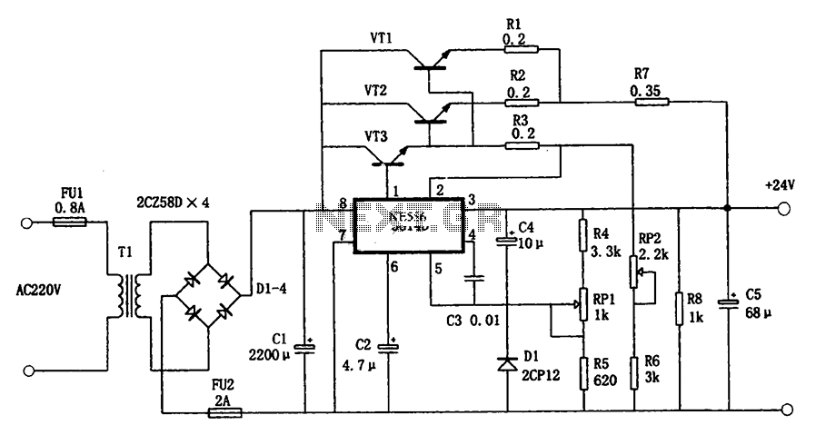
The described power supply circuit is designed to convert an input voltage of 220V AC at 50Hz into a stable +24V DC output, capable of delivering a maximum current of 1.9A. The core of the circuit is the 5G14D integrated voltage regulator, which is responsible for regulating the output voltage. It is important to note that while the 5G14D has a limited output current of 24mA, the inclusion of three external power transistors allows the circuit to handle significantly higher current loads.
The adjustment potentiometer RP1 is integral for fine-tuning the output voltage to ensure that it meets the required specifications. This allows for precise control of the output voltage, accommodating any variations in the input voltage or load conditions. On the other hand, RP2 serves as an adjustable overcurrent protection mechanism, enabling the circuit to prevent damage due to excessive current draw. This is particularly critical in applications where the power supply may be subjected to varying load conditions.
The power supply is designed to maintain an output voltage of 24V with a maximum allowable error of 2%, ensuring that connected devices receive a reliable power source. Additionally, the ripple voltage, which is the AC component superimposed on the DC output, is kept to a minimum at 24mV, indicating a well-filtered output. The overload protection is set at 2.8A, providing a safety margin to prevent damage to both the power supply and the connected load in case of a fault condition.
Overall, this power supply circuit is suitable for various applications requiring a stable and reliable DC voltage, with built-in features for voltage adjustment and overcurrent protection, making it a robust solution for powering electronic devices. As shown in Figure as a + 24V, 1.9A power supply circuit. It 5G14D domestic integrated voltage regulator as the core, three external power transistor, output current from the p ower supply itself 5G14D rated current 24mA, up to 1.9A. RP1 is used to fine-tune the output voltage, RP2 is used to adjust the overcurrent protection point. The main technical features of the power supply: (1) Input voltage: 220V 22V, 50Hz. (2) Output voltage: 24V, error 2%. (3) Maximum output current: 1.9A. (4) The ripple voltage: 24mV. (5) overload point: 2.8A.
Related Circuits
The amplifier drives a pair of speakers using two LM3876 amplifier chip circuits (50 watts per channel) or a pair of headphones with Meier Crossfeed through a clarifier and a dual OPA2134 Opamp. It features four selectable band inputs...
Under the loading condition of the resistance, the output voltage (Uo) variable range is from 30V to 36V, with a maximum output current (Imax) of 2A. When the input voltage (U2) changes from 15V to 21V, the voltage regulation...
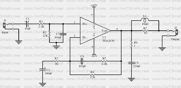
This simple 10 watts audio power amplifier is designed for home-brewed purpose. It is based on an Audio Power Amplifier IC that is called TDA2030. It is a monolithic integrated circuit in Pentawatt package, intended for use as a...
My FM Wireless Microphone has been a very popular project with beginners and experienced constructors alike. It has been used inside guitars and as the basis of a remote control system. I do however, receive many requests for a...
This is a power audio amplifier circuit based on the STK400xx series. It provides high-quality sound and is cost-effective, as the STK40xx series is affordably priced. The circuit can be easily constructed using only a few external components. The...
This universal power supply includes a bridge rectifier, a voltage stabilizer (78xx), and a PNP power transistor. This combination allows for a load current output. The universal power supply circuit is designed to convert alternating current (AC) from the mains...
Warning: include(partials/cookie-banner.php): Failed to open stream: Permission denied in /var/www/html/nextgr/view-circuit.php on line 713
Warning: include(): Failed opening 'partials/cookie-banner.php' for inclusion (include_path='.:/usr/share/php') in /var/www/html/nextgr/view-circuit.php on line 713