
Multi-output power supply circuit

The multi-output power supply circuit is designed to deliver distinct voltage levels required for different applications. The transformer is the primary component, converting the input AC voltage to a lower AC voltage suitable for regulation. The secondary winding of the transformer feeds into the four linear voltage regulators, each tailored to output a specific voltage.
The 7812 voltage regulator is utilized to provide a stable +12V output, suitable for powering devices that require higher voltage levels. The 7805 regulator outputs +5V, commonly used for microcontrollers and digital circuits. The 7905 and 7912 regulators supply -5V and -12V, respectively, which are often necessary for operational amplifiers and analog signal processing circuits.
Each regulator is equipped with input and output capacitors to ensure stability and minimize voltage ripple. The circuit also features a switching mechanism for each output, allowing users to control the availability of each voltage independently. This is particularly useful in experimental setups where different voltage levels are needed at different times.
Output indicators are included for each voltage line, providing visual confirmation that the regulators are functioning correctly and that the desired voltage is present at the output terminals. The design ensures that the circuit remains compact while offering versatility in powering various electronic components and systems.
Overall, this multi-output power supply circuit serves as a reliable and efficient power source for a wide range of electronic experiments and applications, facilitating the development and testing of various devices that require different voltage levels.Shown for the multi-output power supply circuit. The circuit uses the transformer secondary winding and 4 respectively 7812,7805,7905,7912 + 12V, + 5V, -5V and -l2V 4 groups independent output voltages. Each group has a separate output voltage switching control and output instructions. Experiments can be used as power source.
Related Circuits

This is a circuit known as a Wien bridge oscillator. The circuit features both positive and negative feedback loops and operates under the control of an operational amplifier (op-amp). The oscillation frequency is determined by the RC time constant,...
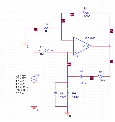
In this laboratory experiment, the objective is to design the frequency-determining network for a 1 kHz sinusoidal oscillator. The specified values are as follows: Capacitance = 100 nF and Resistance = 1520 ohms. The output voltage waveform of the...
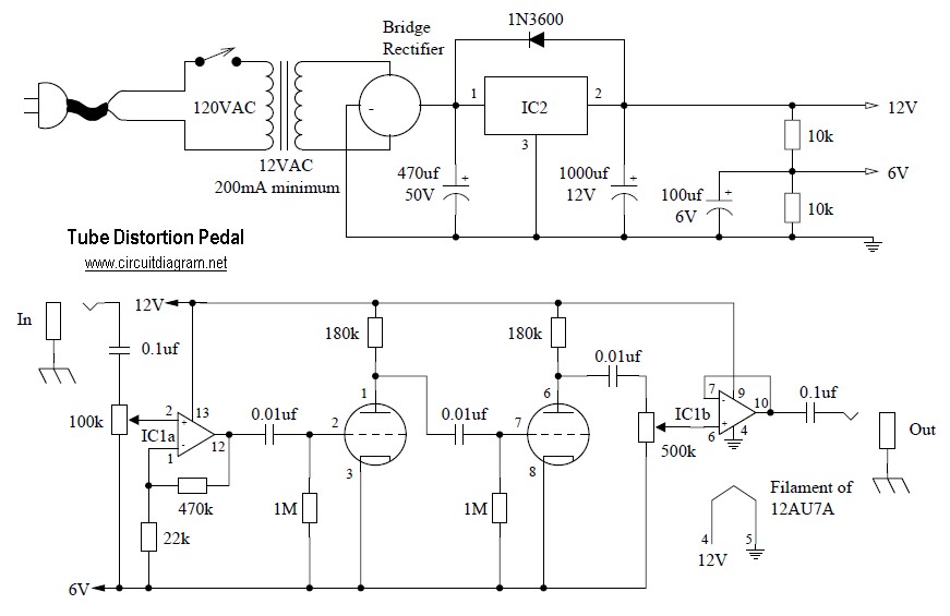
Tube distortion pedal circuit diagram. IC1: 747 dual op-amp; other ICs may be substituted, but the pinout will differ, so the datasheet should be checked. IC2: LM340K-12V voltage regulator. All resistors are 1/2 W. The bridge rectifier is a...

This circuit utilizes the Mitsubishi M65830 Digital Delay chip, which has proven to be simple and effective for applications requiring a fixed delay. The serial data necessary for achieving various delay settings is not readily available and would significantly...
An audio power amplifier can enhance weak signals from devices like tuners, CD players, or tape decks to fill a room with sound. This article emphasizes the operating principles and circuitry of low-frequency power amplifiers utilizing bipolar junction transistors...
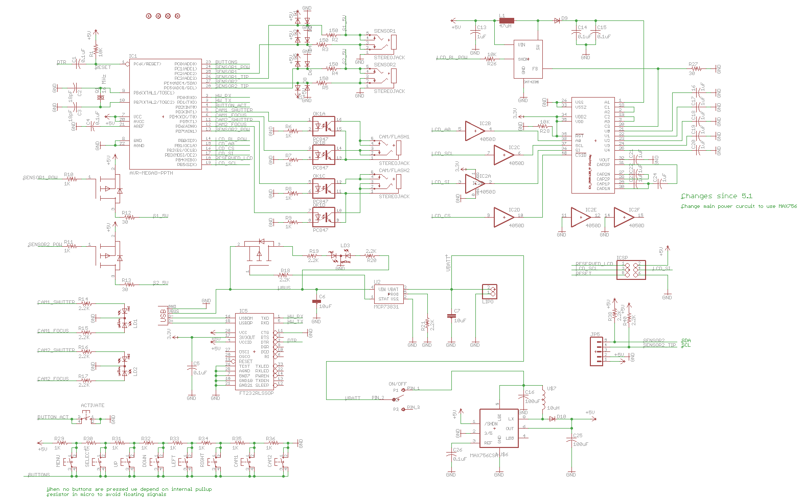
Previously, a linear regulator was used, but a Max756 boost converter is now in operation. An output ripple of 0.1 to 0.3V is observed in the current, while the Max756 datasheet indicates an expected ripple of about 50 mA....