
A circuit diagram of a switching power supply
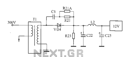
The schematic for the switching power supply includes a transformer with a secondary winding, which is responsible for stepping down the voltage. The output from this winding feeds into the rectifier circuit, which consists of diodes, including VD4, that convert the AC voltage to DC. The filter capacitors, C22 and C23, are critical components that smooth out the rectified output, ensuring a stable DC voltage. The design of the power supply must account for thermal management due to the compact layout within the monitor's base. The proximity of the capacitors to the rectifier diode leads to increased thermal stress, which can accelerate the aging process of the capacitors.
In this scenario, the failure of C22, due to its significant drop in capacitance, has a direct impact on the stability of the 12V output. The power supply's ability to maintain stable voltages for the 5V and 3.3V outputs is a result of their respective regulation circuits, which may compensate for fluctuations in the input voltage. However, the underlying issue with the 12V output remains a concern, as it can lead to potential operational failures in devices relying on this voltage level. Regular maintenance and monitoring of the power supply components, especially in heat-sensitive environments, are essential for ensuring long-term reliability and performance.12V voltage instability, you should first check the switching power supply output section, as shown in FIG. The secondary winding of the transformer and the switch VD4 examination were normal, no inductor L2 Weld phenomenon. Filter capacitors C22 and C23 parameters are 1000pF / 16V, measuring capacitance meter C23, normal (capacity decreased slightly), but the C22 capacity has dropped to less than 80 F, the C22, C23 with the analysis of the reasons is the machine's main power mounted within the base of the monitor, the space is small, poor heat dissipation, and C22, C23 are close to 12V rectifier diode (especially C22 closer together), decreased capacity after being baked to make 12V with a load capacity deteriorates, and then this failure. Although derived from the 5V and 3.3V 12V, 12V instability but not down to 5V and 3.3V supply voltage converter limit or less, so the two voltages have been normal, and thus conceal the nature of the fault.
Related Circuits
The following circuit illustrates the TL084 integrated circuit (IC) used as a dynamo current voltage regulator, accompanied by a fuse box diagram. Features include a comprehensive control circuit that will... The TL084 is a quad operational amplifier that is commonly...
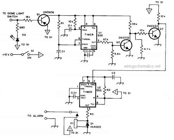
This circuit diagram represents a smart car alarm timer. This design is more advanced compared to traditional car alarm systems. When activated, the alarm remains active for 80 seconds, following an initial delay of 15 seconds. The smart car alarm...
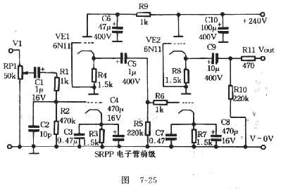
The FET amplifier is designed for enthusiasts who prefer tube sound but cannot utilize traditional tube amplifiers. It exhibits output characteristics similar to bipolar FET tube amplifiers, featuring good frequency response and sound quality comparable to tube amplifiers. Coupling...
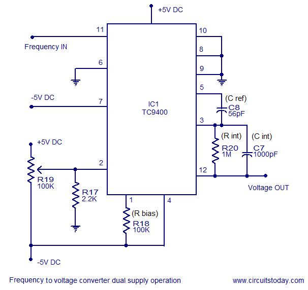
A simple frequency to voltage converter circuit designed around the TC9400 F to V / V to F converter IC. Dual and single supply versions are provided. The TC9400 is a versatile integrated circuit that converts frequency signals into corresponding...
The car battery charging current is automatically limited to 4.2A. If there is a 600mV voltage on R1 (indicating 4A flowing through it), the T1 transistor begins to conduct. This prevents excessive charging current as the base current of...
Boiling water or cooking with a gas stove can sometimes lead to the fire being extinguished due to water spills, which can result in a significant gas overflow and pose a risk of poisoning. This example describes a stall...