
power supply adjustable 0v 30v dc2a
The described circuit is an effective linear voltage regulator that utilizes the LM723 integrated circuit, known for its reliability and versatility in power supply applications. The LM723 serves as the primary control element, maintaining a stable output voltage by adjusting the base current of the power transistor Q1, which in this case is a 2N3055. This NPN transistor is capable of handling high currents, making it suitable for applications requiring significant power output.
The potentiometer R1 plays a critical role in setting the output voltage. By adjusting R1, the user can vary the feedback voltage to the LM723, which in turn adjusts the base voltage of the 2N3055, allowing for precise control over the output voltage within the specified range. It is important to note that the output voltage is limited by the transformer TR1's specifications. A transformer capable of supplying adequate current is necessary to achieve the desired 30V output; inadequate current supply will result in a lower output voltage, typically around 26V.
The selection of a proper heatsink for the 2N3055 is crucial, as this transistor will dissipate significant heat during operation, especially under high load conditions. Without adequate thermal management, the transistor may overheat, leading to thermal shutdown or permanent damage. Therefore, a heatsink with appropriate thermal conductivity and surface area should be employed to maintain safe operating temperatures.
In addition to the heatsink, the choice of potentiometer R1 is also important. A high-quality potentiometer will ensure stable and reliable voltage adjustments, minimizing noise and improving overall circuit performance. The circuit may also benefit from the inclusion of bypass capacitors near the LM723 and the power transistor to filter out any high-frequency noise and improve transient response.
Overall, this regulated power supply circuit is a practical solution for various electronic projects requiring adjustable DC voltage, offering simplicity in design while maintaining the capability to deliver stable output under varying load conditions.It is a simple circuit regulated power supply, based on the known LM 723, that drive a transistor Q1 [2N3055]. The regulation of voltage, of expense becomes with potentiometer R1 from 0v-30v DC roughly. In order to we achieve 30 V, will should the transformer of supply TR1, it gives all the current that it asks the load, differently the output voltage it will be found in the levels of 26 V roughly.
Essential is the use of a good heatsink for transistor Q1, as well as good quality of potentiometer in the place of R1.. 🔗 External reference
Related Circuits
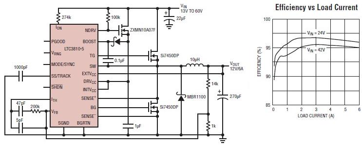
The LTC3810-5 synchronous step-down switching regulator controller can be used to design a simple and efficient 12-volt switching power supply electronic project with minimal external components. This controller is capable of stepping down voltages from up to 60V, making...
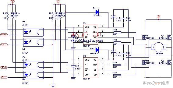
The drive circuit for the electromotor comprises a FET bridge circuit, a FET base drive circuit, a current sensor for the motor drive circuit, and a relay. The FET bridge circuit primarily consists of four high-power MOSFETs, which must...
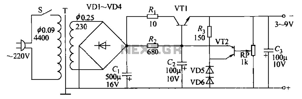
A 3-9V adjustable 100mA power supply is presented, featuring a series regulator circuit that utilizes amplifier tubes. The output voltage can be continuously adjusted between 3V and 9V, with a maximum output current of 100mA, making it suitable for...
The success or failure of lighting upgrades depends on the quality of components and workmanship. Proper wire routing is essential to prevent insulation chafing. The quality of soldering connections is crucial, as poor solder joints can corrode and fail....
The National Semiconductor LMV225 is a linear RF power meter integrated circuit (IC) housed in a surface-mount device (SMD) package. It operates within a frequency range of 450 MHz to 2000 MHz and requires only four external components for...
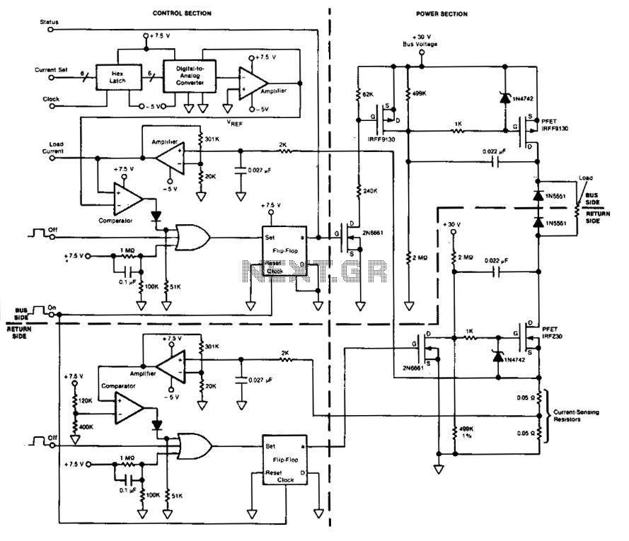
This circuit facilitates on/off switching, soft starting, current monitoring, current tripping, and overcurrent protection for a 30 Vdc power supply, accommodating normal load currents of up to 2 A. The switch is activated by an "on" command pulse and...