
power supply Inductive choke with bypass capacitors
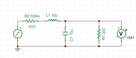
The described circuit employs an inductor and a decoupling capacitor to form a resonant LC circuit, which is commonly utilized in power supply filtering applications. The inductor serves to store energy in a magnetic field, while the capacitor stores energy in an electric field. The interaction between these two components gives rise to the circuit's resonant frequency, which can be calculated using the formula:
\[ f_r = \frac{1}{2\pi\sqrt{LC}} \]
where \( f_r \) is the resonant frequency, \( L \) is the inductance in henries, and \( C \) is the capacitance in farads. At this frequency, the impedance of the circuit is minimized, allowing signals at this frequency to pass through with little attenuation, while signals outside this frequency range experience significant attenuation.
In practical applications, the presence of a purely resistive load allows for the assessment of how the LC circuit responds to various load conditions, particularly in terms of noise suppression. The observed high-frequency noise reduction aligns with theoretical expectations, as the circuit effectively acts as a low-pass filter, attenuating frequencies above the resonant frequency.
However, the amplification of noise at approximately 20 kHz indicates a potential resonance issue. This spike may arise from the circuit design, where the selected values for the inductor and capacitor inadvertently align with this frequency, resulting in an undesirable amplification of noise rather than attenuation. The implications of this behavior are significant for power regulation, as it suggests that while the LC circuit is effective at filtering high-frequency noise, it may inadvertently enhance noise at certain frequencies, complicating the overall performance of the power supply.
The question regarding the sufficiency of bypass capacitors in creating an RC filter is also pertinent. Bypass capacitors are typically used to shunt high-frequency noise to ground, and their effectiveness is largely dependent on their capacitance value and the layout of the circuit. If the capacitance value is too small, the filter may not adequately attenuate the noise at critical frequencies. Additionally, the physical characteristics of the capacitors, such as Equivalent Series Resistance (ESR) and Equivalent Series Inductance (ESL), can affect performance.
In conclusion, while the LC circuit demonstrates effective noise reduction capabilities, the resonant frequency behavior must be carefully considered in power regulation applications. Further investigation into the values of the inductor and capacitor, as well as the overall circuit design, may be necessary to mitigate the amplification of noise at the resonant frequency and ensure optimal performance in real-world scenarios.Using an inductor inline and a decoupling capacitor it`s creating essentially a series LC circuit. Now one of the properties of LC circuits is they have a resonant frequency. I modeled a LC circuit with an attached purely resistive load to simulate what the circuit did under different kinds of loads: As expected high frequency noise is very effectively reduced (if I`m not mistaken, outside the peak region it should decay at 40 dB per decade). However, there is that ominous spike at around 20 kHz where noise is actually being very effectively amplified from the resonant frequency. Is this typically not a factor when it comes to regulating power to a board Why isn`t the RC filter created using bypass capacitors enough Is it because the capacitor size required for an effective RC filter is too high Or am I missing something in my model
🔗 External reference
Related Circuits
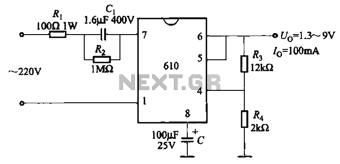
The output voltage can be calculated as follows: U = 1.3 (1 + R3 / R4) (V), where R3 and R4 are part of an adjustment potentiometer, allowing for a continuously adjustable output voltage. The described circuit involves a voltage...
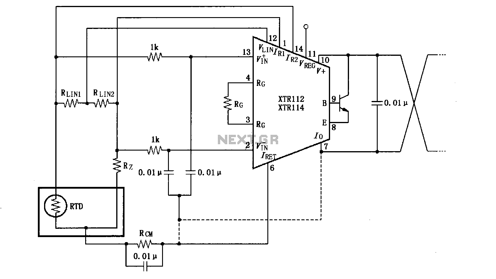
The length of the transmission wire in a current loop circuit can introduce radio frequency (RF) interference. This RF energy may lead to input errors in sensitive devices such as the XT112/114, causing instability in loop current or input...
With the increase in the variety of modern electrical equipment for vehicles and the rise in power levels, there is a growing demand for different types of power supplies, including AC and DC sources. The power system needs to...
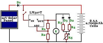
The circuit is designed to power a CCTV camera, provide lighting inside a nestbox, and charge batteries using a photovoltaic (PV) solar panel. It includes a circuit diagram for a solar-powered wireless CCTV camera with battery backup. D1 is...
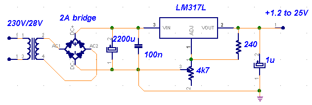
The LM317 is a versatile and efficient voltage regulator capable of delivering an output voltage range of 1.2V to 37V and a maximum current of 1.5A when used with an appropriate heat sink. This circuit is suitable for a...
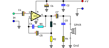
This compact amplifier is built around the TDA2003 integrated circuit, which can deliver 4W RMS at a 4-ohm load. The TDA2003 offers enhanced performance while maintaining the same pin configuration as the TDA2002. It retains the advantageous features of...