
lm317 variable power supply
The LM317 voltage regulator circuit is designed to provide a stable output voltage that can be adjusted according to the requirements of the application. The circuit typically consists of the LM317 integrated circuit, input and output capacitors, and resistors for setting the output voltage.
The input voltage must be higher than the desired output voltage by at least 3V to ensure proper regulation. The LM317 requires a minimum load current to maintain regulation, which can be achieved by connecting a load resistor if the actual load is too light.
For voltage adjustment, two resistors are connected in a voltage divider configuration between the output and the adjustment pin of the LM317. The output voltage (Vout) can be calculated using the formula:
Vout = 1.25V * (1 + R2/R1) + Iadj * R2
Where Iadj is typically very small and can often be neglected for most applications.
Input and output capacitors are recommended to ensure stability and transient response. A typical configuration might include a 0.1µF ceramic capacitor at the input and a 1µF tantalum capacitor at the output.
The LM317 is housed in a TO-220 package, which allows for easy mounting on a heat sink, ensuring that it can dissipate heat effectively during operation. This is particularly important when operating at higher currents, as excessive heat can lead to thermal shutdown or damage to the regulator.
In summary, the LM317 voltage regulator circuit is a robust solution for providing adjustable power supply voltages in various electronic projects, making it a staple component for hobbyists and professionals alike.A truly timeless circuit. LM317 is a versatile and highly efficient 1.2-37V voltage regulator that can provide up to 1.5A of current with a large heat sink. It`s ideal for just about any application. This was my first workbench power supply and I still use it.. 🔗 External reference
Related Circuits
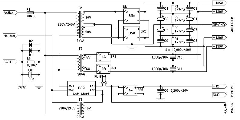
Power supply for a 1500-watt audio power amplifier. This power supply circuit is paired with a high-power audio amplifier rated at 1500 watts. A serious approach is required to design the power supply for the amplifier. First, a step-down...
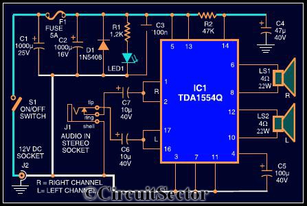
The circuit diagram illustrates a robust stereo amplifier capable of delivering 22W of power. It is based on the widely used single-chip audio power amplifier TDA1554Q (IC1), which is configured as two 22W stereo bridge amplifiers. While listening to...
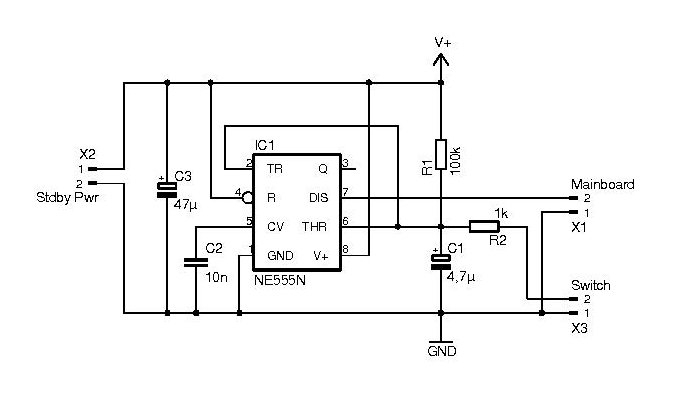
Automatic power switch for ATX power supplies. Visit the page to read the explanation about the related circuit diagram. The automatic power switch for ATX power supplies is a circuit designed to manage the power-on and power-off states of an...

This circuit adds a power down function to analog I/O ports (for example, the AD7769 and AD7774). Moreover, the diodes ordinarily needed to protect the devices against power-supply missequencing can be eliminated. Bringing the power down control high (+5V)...
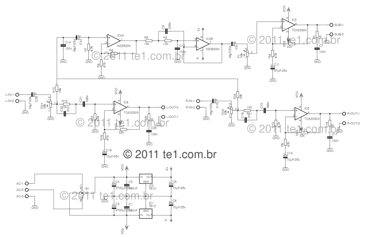
This circuit is a complete application for a 2.1 amplifier system, featuring two satellite speakers for TDA and one subwoofer. It is commonly used in commercial applications to enhance the audio output of computers using a stereo amplifier along...
For the 60W amplifier, a nominal (full load) supply of +/- 35V is required, so a 25-0-25 secondary is ideal - however, see Updates, below. The circuit for the supply is shown below, and uses separate rectifiers, capacitors and...