
Power supply protection circuit

In this circuit, the primary function is to ensure the protection of sensitive equipment from overvoltage conditions. The design includes a voltage regulator that steps down the input voltage from 12 V to a stable 5 V. The trip mechanism is critical; it is configured to activate at 5.7 V, slightly above the desired output voltage, providing a buffer to prevent damage to the load.
The voltage divider formed by the 330-ohm resistor and the 500-ohm potentiometer is essential for monitoring the output voltage. The adjustable potentiometer allows for fine-tuning of the voltage divider ratio, enabling precise voltage sampling. The output voltage is continuously monitored, and if it surpasses the trip voltage, the SCR becomes conductive, effectively shorting the fuse and causing it to blow. This action interrupts the circuit and protects the downstream components.
The 2N2906 transistor is utilized as a switch that is normally off, controlled by the SCR and the 10 kΩ resistor. The LED indicator serves as a visual alert, illuminating when the output voltage exceeds the safe threshold. The 2N3906 transistor acts as an additional control element, receiving base current when the SCR conducts, ensuring that the LED lights up to signal an overvoltage condition.
Overall, this circuit design exemplifies a robust approach to voltage regulation and overvoltage protection, combining passive and active components to create a reliable safeguard for electronic equipment.When using a regulated supply to reduce a supply voltage there is always the danger of component failure in the supply and consequent damage to the equipment. A fuse will protect when excess current is drawn, but might be too slow to cope with overvoltage conditions.
The values shown are for a 12 V supply being dropped to 5 V. The trip voltage is set to 5.7 V to protect the equipment in the event of a regulator fault. The 330 ohm resistor and the 500 ohm potentiometer form a potential divider which samples the output voltage as set by adjustment of the potentiometer. The SCR is selected to carry at least twice the fuse rating. The full supply voltage is connected to the input of the regulator. The 2N2906 is held bias off by the 10 k resistor and the SCR so that the LED is held off. If the output voltage rises above a set trip value then the SCR will conduct, the fuse will blow, and the 2N3906 will be supplied with base current via the 10 k resistor, and the LED will light up. 🔗 External reference
Related Circuits

The circuit illustrated is a typical configuration for the LM4916 two-channel amplifier. The left and right channel audio signals are fed into the LM4916, which amplifies them internally. The output is then delivered through a coupling capacitor (Co) to...
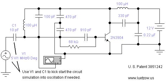
The oscillator circuits presented on this page are derived from expired or non-maintained U.S. Patents. All circuits are formatted for "Electronic Workbench 5.12" or "Multisim 7" circuit simulation software. A note regarding SPICE simulation of electronic oscillator circuits: all...

The circuit consists of a sound detection circuit and a monostable trigger circuit that activates a relay. VT1 amplifies the input audio signal. When a signal is detected, the 555 timer is triggered, pulling K. Simultaneously, VT2 conducts, allowing...

A circuit has been designed to detect the duration of an ultrasonic pulse as it travels a certain distance. The input signal is sourced from a 40 kHz ultrasonic receiver. The first stage consists of a 40 kHz band-pass...
Transistors are configured as a Darlington pair in this circuit. A thermistor is utilized to detect or sense heat. A 12K variable resistor is employed to adjust the activation of the buzzer at the desired temperature. The operation of...
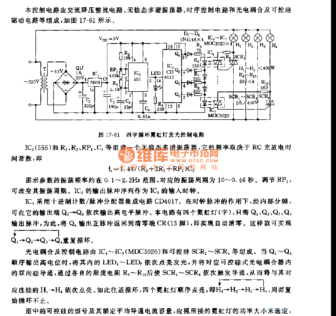
This control circuit consists of an AC step-down rectifier circuit, an astable multivibrator, a timing control circuit, an optocoupler circuit, and an SCR driving circuit, as illustrated in Figure 17-61. The astable multivibrator is formed using IC2 (555), resistors...