
Power Supply Schematic

The power transformer design incorporates multiple secondary windings to provide various voltage levels necessary for different operational components of the system. The 720V center-tapped secondary is crucial for both the plate and screen supplies, while the 6.3V secondary serves the tube filament and bias power supply. The unused 5V secondary allows for an increased current draw from the high voltage secondary without risking overloading the transformer.
The full-wave bridge rectifier configuration, composed of two pairs of series-connected 1N4007 diodes, is essential for converting the AC voltage from the transformer into usable DC voltage. This configuration ensures that the rectifier can handle the voltage and current requirements of the plate supply effectively. The choke input filter is a critical component, filtering out the AC ripple from the rectified DC, allowing for a smoother and more stable output voltage, which is vital for the reliable operation of the amplifier.
The inclusion of bleeder resistors is a safety feature, ensuring that the filter capacitors discharge when the unit is powered down, thereby reducing the risk of electric shock. Additionally, these resistors provide a load to stabilize the output voltage during idle periods, preventing excessive voltage buildup that could potentially damage components.
The voltage regulation for the screen supply is particularly important in maintaining linear operation of the amplifier. The use of gaseous regulator tubes provides a stable voltage as long as the current remains within specified limits, ensuring consistent performance and minimizing distortion. The design takes into account the thermal characteristics of the components, ensuring that the dropping resistor is appropriately sized to prevent overheating during operation.
Overall, the design of the power supply in the 6146B transmitter exemplifies a careful balance of component selection and configuration to achieve reliable performance, safety, and operational efficiency.The power transformer has three secondaries: 720V at 120mA center-tapped for the plate and screen supplies, 6. 3V at 3. 5A for the tube filament and bias power supply, and 5V at 3A (not used). Since the 5V secondary is not used, a little more current than 120mA can safely be drawn from the high voltage secondary.
The high voltage secondary feeds a c onventional full wave bridge rectifier to convert the AC to unfiltered DC, which is then fed to the plate power supply filter. Since the the PIV rating of one diode is not enough, two must be used in series, so the four diodes D1 through D4 are actually two 1N4007 diodes in series.
For the purposes of the plate supply, the transformer center tap is not used. However, the center tap is used for the screen supply. The output from the plate rectifier is direct current (DC) but with a large alternating current (AC) component superimposed. The output from the rectifier in fed to a choke input filter. The filter choke allows the DC component to flow through, while offering a very high impedance to the AC component.
The filter capacitors are essentially an open circuit to the DC, but they effectively short circuit the AC component to ground. The result is that little of the AC component reaches the output. Since the capacitors have a maximum rating of 450V, two are used in series to form a 900V 50uf capacitor.
Two 40k, 10W bleeder resistors in parallel with each of the capacitors serve several important functions: (a) They bleed off the charge on the filter capacitors when the unit is shut off, preventing the possibility of a dangerous electric shock that could occur even though the unit were turned off and unplugged. (b) They provide a minimum load on the power supply to prevent the output voltage from soaring during standby periods.
(c) They equalizes the voltage across the filter capacitors. The power supply in the 6146B transmitter is a design commonly called an "Economy Supply". This design makes use of the power transformer and rectifiers in a very clever manner. All four diodes are used to form a full wave bridge rectifier for the plate supply, but for the screen supply, only diodes D1 and D2 are used. These two diodes, along with the transformer center tap, form a conventional full wave center tapped rectifier.
The output of this rectifier is half that of the plate supply. This then feeds the screen filter. The output from the screen rectifier is then fed to the screen filter, which is a choke input filter which functions exactly the same as the plate supply filter. The screen filter then feeds the screen regulator. The output of the screen filter is fed to a voltage regulator that keeps the voltage at a constant 180V, unless the current exceeds the maximum value for the 6146B.
The voltage then starts to fall off. Regulated screen voltage is very important in a linear amplifier, since the tube operation is sensitive to variations in screen voltage. If the screen voltage varies with the signal, the tube will not operate linearly, and distortion of the signal results.
Gaseous regulator tubes such as the 0C3 and OA3 have the property that as long as the current through them is between about 4mA and 30mA the voltage across the tube is constant. When such tubes are placed in series they act as a single tube that operates at the sum of their voltages.
The value of the dropping resistor (5k in this case) is quite critical. The resistor must be selected so that the regulator tubes remain lit if the screen current is 15mA or less, but extinquish if the current goes over about 17mA (the maximum permissible value for the 6146B at a screen voltage of 180V). If the resistor value is too low, it is possible to damage the tube by overheating the screen, as can easily happen during amplifier tune-up.
When the proper value is selected, the screen voltage stays constant during normal operation, but drops if too much current is drawn, li 🔗 External reference
Related Circuits
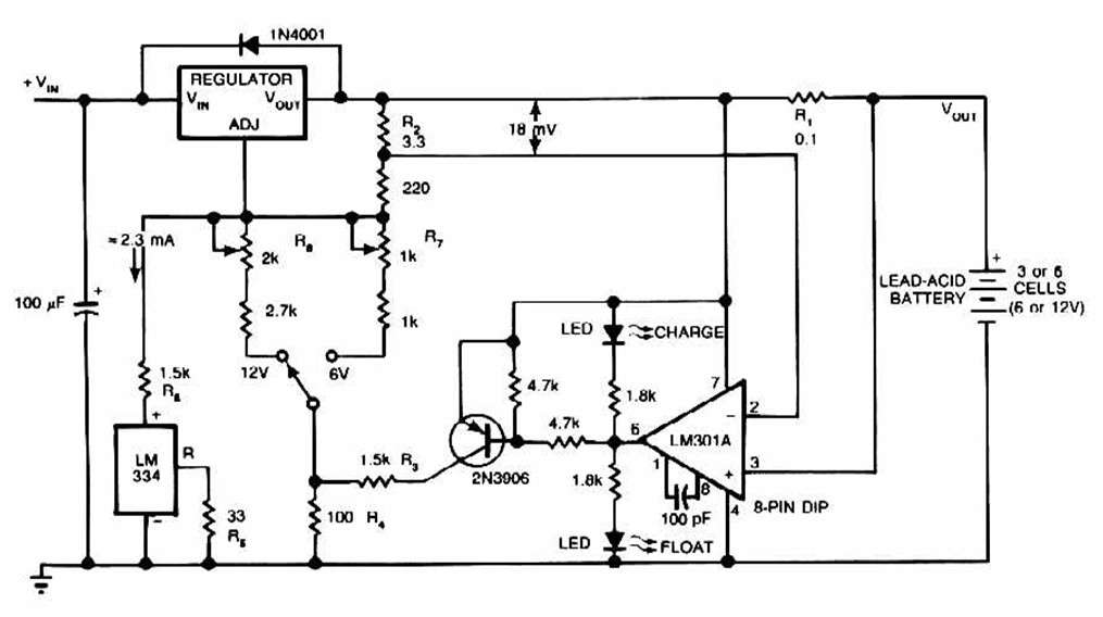
The schematic for this charger is straightforward. It is designed to charge a Gel Cell or other lead-acid types. This simple battery level monitor circuit can indicate the charging process in a 12 Volt lead-acid battery or tubular battery....
This very simple and self-powered device was conceived to allow a person to monitor if someone has rung his home door-bell when he was out. As most door-bells use 12Vac supply, the circuit must be simply connected to the...
The transformer can be selected based on the required maximum voltage and current output. Recommended options include: 36V, 40V, or 48V center-tapped configurations, with power ratings of 50VA, 75VA, 80VA, or 100VA. It is essential to mount Q4 on...
40V regulated power supply based on TIP42A and LM317. Refer to the specified page for an explanation of the related circuit diagram. The 40V regulated power supply utilizes a TIP42A transistor and an LM317 voltage regulator to provide a stable...
It will accept AC from 6v to 18v or DC from 9v to 18v and any current up to 1 amp. The diode bridge on the input converts AC to DC and it doesn't matter which way around the...
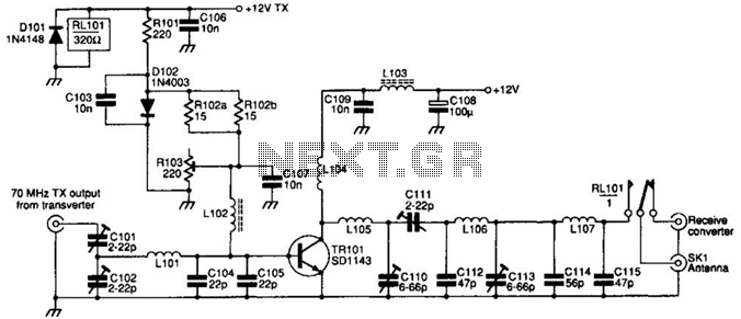
The SD1143 transistor offers a gain of approximately 14 dB in this circuit. Its design takes advantage of the fact that a 175-MHz device exhibits significantly higher gain when operated at lower frequencies. The amplifier was initially intended for...