
power supply Transistor current limiter microcontroller controlled
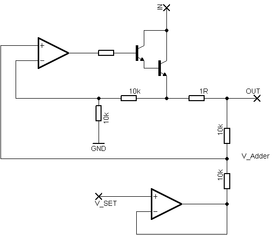
To design a circuit that utilizes Rsense to control the conduction of Q2 based on a sensed voltage, a high-side current sensing configuration is recommended. In this setup, Rsense is placed in the high side of the load, allowing for the measurement of current flowing through the load without interrupting the circuit. When the voltage across Rsense exceeds the threshold of 0.65V, Q2 is triggered to conduct, which can be accomplished by connecting Q2 to a comparator circuit.
The comparator can take the voltage across Rsense as one input and a reference voltage defined by the microcontroller as the other input. This reference voltage can be set to any desired limit, allowing for flexibility in current control. The output of the comparator can then be used to drive the gate of Q2, turning it on when the sensed voltage exceeds the reference voltage.
Rbias plays a critical role in this configuration, as it can be used to establish a desired current limit by creating a voltage divider with Rsense. By adjusting Rbias, the threshold voltage at which Q2 conducts can be fine-tuned. If Rbias is not implemented, the circuit may not effectively limit the current to the desired level, resulting in potential overcurrent conditions.
To initiate the limiting process, the microcontroller can periodically sample the voltage across Rsense. When the sensed current is sufficient to trigger the comparator, the microcontroller can take appropriate actions, such as reducing the duty cycle of a PWM signal or activating a control signal to limit the load current.
In summary, a well-designed circuit using Rsense and a comparator can provide an effective means of controlling current through a load. The combination of Rsense, Rbias, and a microcontroller allows for dynamic adjustment of the current limit without the need for a digital potentiometer, ensuring both flexibility and precision in current control applications.Rsense would cause Q2 to conduct if at a threshold (0. 65V assumably) and Rbias will determine how much it will be limited, however that is unclear to me, especially if Rsense will be somewhere highside and just turning on Q2 with my uC seems to not do anything (in simulation at least) How would I come up with the formulas for a variable limit that I can control I would rather not have to use a digital potentiometer in place of R2, if I can somehow have sense voltage compared with a comparator with a voltage my uC defines, that`d be great! But how could I start the limiting What do I "turn on" when the sense resistor shows enough current Does Rbias have to be there to limit it to a certain level, and I`ll end up having to use a digipot anyway
🔗 External reference
Related Circuits
The circuit can produce about 250-500mA at 2KV, depending on the transformer. For C1, you can use the capacitor out of an old microwave. This circuit is mainly provided as a demonstration of using commonly available parts for something...
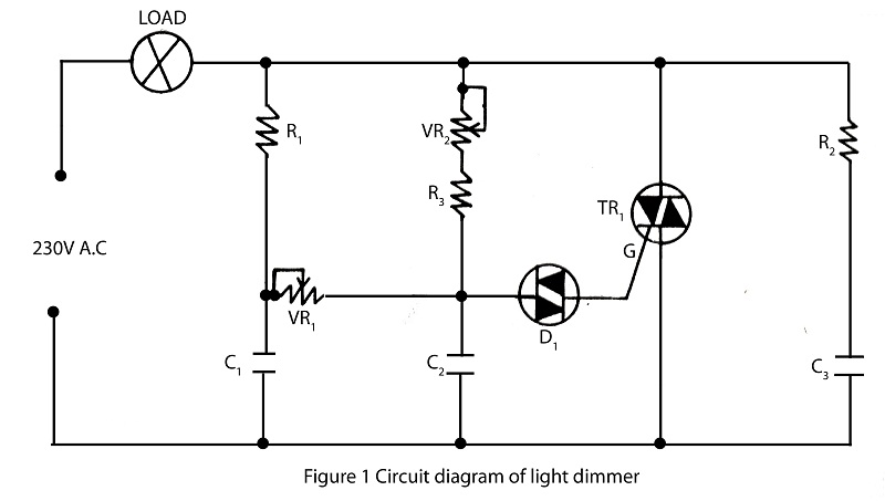
The lighting source, such as a bulb or tube light, illuminates based on its specified wattage. To achieve increased brightness, a higher wattage bulb must be used, while a lower wattage bulb is necessary for reduced brightness. However, it...

In telecommunications, Frequency Modulation (FM) transmits information over a carrier wave by varying its frequency. FM is widely utilized at VHF radio frequencies for high-fidelity broadcasts of music and speech. The global broadcast band is situated within the VHF...
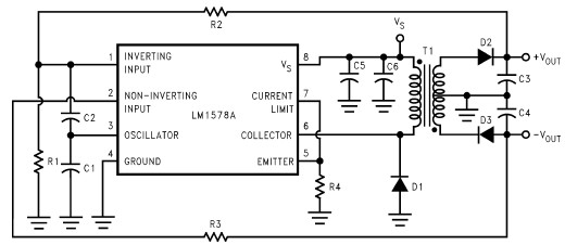
This RS232 power supply circuit diagram is a simple RS-232 line driver power supply that operates from an input voltage as low as 4.2V and delivers an output of ±12V at ±40 mA with an efficiency of better than...
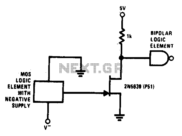
This simple circuit facilitates level shifting from any logic function (such as MOS) operating from a negative to ground supply to any logic level (such as TTL) operating from a positive to ground supply. The 2N5639 transistor offers low...
C1 is a 1000 microfarad aluminum electrolytic capacitor. For loads less than 100mA, a 220 microfarad capacitor can be substituted. The voltage rating should be 2.5 times the output voltage. C1 serves as a critical component in various electronic circuits,...