
Single Transistor FM Transmitter Design

1. The tuning of the FM transmitter to the desired frequency is crucial. Even minor variations in the coil specifications or slight adjustments in the variable capacitor can shift the harmonic frequency outside the 88-108 MHz FM band. A condenser microphone (MIC) is employed to capture sound signals. The diaphragm within the MIC vibrates in response to changes in air pressure, generating alternating current (AC) signals. A variable resistor (VR1) adjusts the current flowing through the MIC, thereby determining its sensitivity. For optimal sensitivity, the condenser MIC should be directly soldered onto the printed circuit board (PCB). Enclosing the MIC in plastic tubing can significantly enhance its sensitivity.
C1 serves as the first decoupling capacitor, impeding various frequencies of speech signals and modulating the current to the base of the transistor. A 4.7 µF capacitor isolates the microphone from the base voltage of the transistor, allowing only AC signals to pass. Larger capacitors tend to emphasize bass frequencies, while smaller ones enhance treble frequencies. Capacitor C2 (0.01 µF) acts as an additional decoupling capacitor. Capacitor C3, positioned across the transistor T1, maintains oscillation in the tank circuit. As long as current flows through the inductor coil L1 and the trimmer capacitor, the tank circuit (coil-trimmer) will resonate at its natural frequency. Continuous oscillation can lead to frequency decay due to heating, but the presence of capacitor C3 prevents this decay. A capacitor value between 4 and 10 pF is recommended.
Variable resistor VR1 regulates the current through the MIC. The voltage divider formed by resistors R1 and R2 limits the base current of T1, while resistor R3 acts as an emitter current limiter. These component values are essential for the performance of the 2N 2222A transistor, a commonly used NPN transistor in general-purpose amplification applications, with a maximum power rating of 0.5 Watts. To avoid overheating and potential damage, the maximum power output should be limited to approximately 125 milliwatts. The pin configuration of the 2N 2222A is as follows: pin 1 is the emitter, pin 2 is the base, and pin 3 is the collector (EBC) when viewed from the front.
The inductor in this circuit is a handmade coil constructed from 22 SWG enameled copper wire. Key parameters such as length, inner diameter, and the number of turns must be considered to ensure the inductor resonates within the 88-108 MHz FM frequency range. For this design, the coil radius was chosen to be 0.26 inches for the outer diameter and 0.13 inches for the inner diameter. The coil can be wound around a screwdriver of the same diameter to create a 5-turn coil measuring 0.2 inches in length. After removing the coil from the screwdriver, the air core coil can be used, with the enamel stripped from the ends for soldering to the transistor.
A small button-type variable capacitor with a value of 22 pF is utilized to fine-tune the resonant frequency of the tank circuit. The variable capacitor and inductor coil together form the tank circuit (LC circuit) that resonates within the 88-108 MHz range. In this tank circuit, the capacitor stores electrical energy between its plates, while the inductor stores magnetic energy induced by the coil's windings. The resonant frequency can be calculated using the appropriate formula. Every FM transmitter requires an oscillator to generate the radio frequency (RF) carrier waves. The term "tank circuit" derives from the LC circuit's ability to store energy for sustained oscillations, with the reactive components C and L solely responsible for energy storage.In Telecommunications, Frequency Modulation (FM) conveys information over a carrier wave by varying its frequency. FM is commonly used at VHF radio frequencies for high-fidelity broadcasts of music and speech. Throughout the world, the broadcast band falls within the VHF part of the radio spectrum. Usually 87. 5 108. 0 MHz is used to transmit an d receive the FM signals. Designing and assembling an FM transmitter is a difficult task. The Note given here explains how a simple FM transmitter is designed and assembled. 1. Tuning of the FM transmitter to the desired frequency. Even a slight change in the coil specification or slight change in the variable capacitor value can shift the harmonic frequency instead of the 88-108 MHz FM band. The condenser MIC is used to pick up the sound signals. The diaphragm inside the MIC vibrates according to the air pressure changes and generates AC signals.
Variable resistor VR1 adjusts the current through the MIC and thus determines the sensitivity of MIC. The condenser MIC should be directly soldered on the PCB to get maximum sensitivity. Sleeving the MIC inside plastic tubing can increase its sensitivity enormously. C1 is the first decoupling capacitor impedes the different frequencies of speech signals. C1 modulates the current to the base of transistor. The 4. 7 uF capacitor isolates the microphone from the base voltage of the transistor and only allows alternating current (AC) signals to pass.
A large value capacitor induces bass (low frequencies) while a low value one gives treble (high frequencies). Capacitor C2 (0. 01) act as the decoupling capacitor. Capacitor C3 across the transistor T1 keeps the tank circuit vibrating. As long as the current exists across the inductor coil L1 and the Trimmer capacitor, the tank circuit (Coil-Trimmer) will vibrate at the resonant frequency.
When the tank circuit vibrates for long time, the frequency decays due to heating. Presence of the capacitor C3 prevents this decay. A capacitor between 4 and 10 PF is necessary. Variable resistor VR1 restricts the current through the MIC. The voltage divider R1 and R2 limits the base current of T1 and R3 forms the emitter current limiter. The given values are necessary for the 2N 2222A transistor. 2N 2222A is the common NPN transmitter used in general purpose amplifications. It has maximum power rating of 0. 5 Watts. Over powering of 2N 2222A can generate heat and destroy the device. So maximum power output should be around 125 milli watt. Pin assignment of 2N 2222 A is 1 Emitter 2 Base 3 Collector (EBC) from the front side The inductor used in the circuit is a hand made coil using 22 SWG (Standard Wire Gauge) enameled copper wire.
The length, inner diameter, number of turns etc are the important parameters to be considered while making the inductor. Then only the inductor resonates in the 88-108 band FM frequency. For this circuit, the coil radius was selected as 0. 26 inches (outer diameter) and 0. 13 inner diameter. Coil can be wound around a screw driver (with same diameter) to get a 5 turn coil of 0. 2 inch long. Remove the coil from the screw driver and use the 5 turn Air core coil. Remove the enamel from the tips and solder close to the transistor. A small button type variable capacitor with a value of 22 pF can be used to adjust the resonant frequency of the tank circuit.
The variable capacitor and the inductor coil form the Tank circuit (LC circuit) that resonates in the 88-108 MHz. In the tank circuit, the capacitor stores electrical energy between its plates while the inductor stores magnetic energy induced by the windings of the coil.
The resonant frequency can be calculated using the formula Every FM transmitter needs an oscillator to generate the radio Frequency (RF) carrier waves. The name Tank` circuit comes from the ability of the LC circuit to store energy for oscillations. The purely reactive elements, the C and the L simply store en 🔗 External reference
Related Circuits
Here is a simple schematic of a TV transmitter circuit, or video transmitter circuit, capable of broadcasting in the VHF range from 60 to 200 MHz. The input video source can be any CCD camera or VCR. The output...
Connect two 24 V / 3 W bulbs in parallel to the output and set the right frequency on PLL. Now turn on the transmitter. You should tune it on a receiver. Maybe you might stretch coils of the...
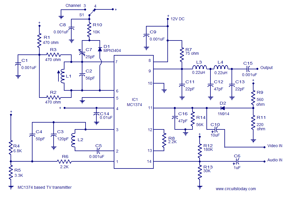
A simple TV transmitter circuit utilizing the TV modulator circuit IC MC1374. It operates with a 12V supply and is capable of broadcasting on channel 3 or 4, employing FM modulation for sound transmission. The TV transmitter circuit based on...
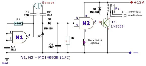
This fluid level sensor circuit is designed to use an AC sensing signal to prevent electrolytic corrosion on the probes. The rectified AC signal is utilized to drive a T1 transistor, which in turn activates a 12-volt relay that...
The variable frequency power supply is a crucial component of the power system, as its characteristics significantly impact the security and reliability of the overall system. The modern variable frequency power supply is characterized by low power consumption and...
A simple whole house FM transmitter circuit diagram and description. Operating power is a 1.5V battery of any type. This circuit is able to transmit at a distance of 30 meters. The whole house FM transmitter circuit operates on a...