
Powerful LED flasher

The circuit operates by leveraging the characteristics of transistors and MOSFETs to create a flashing effect for the LED. The oscillator formed by Q1 and Q2 generates a square wave signal, which oscillates between high and low states. The timing of this oscillation is controlled by the resistor-capacitor (RC) network connected to the base of Q1, determining the pulse width and frequency.
Transistor Q3 serves as a signal inverter, converting the output from the oscillator into a complementary signal that is suitable for driving the MOSFETs. MOSFET Q4 further processes this signal, ensuring that it can handle the power requirements necessary to drive the high power LED effectively.
MOSFET Q5 acts as a switch that allows current to flow through the LED D1 when it receives the appropriate signal from Q4. The LED is connected in series with a current-limiting resistor to prevent excessive current from damaging the LED. The choice of a 1W high power LED allows for bright illumination, making this circuit suitable for various applications where high visibility is required.
The overall design emphasizes efficiency and reliability, making use of solid-state components to achieve the desired flashing effect. The circuit can be powered by a suitable DC voltage source, ensuring that all components operate within their specified limits. Proper heat dissipation measures should also be considered for the MOSFETs and the LED to maintain performance and longevity.This is the circuit diagram a powerful LED flasher. High power LEDs are very common in the market now and a 1W high power LED is used here. Transistors Q1 and Q2 are wired as an oscillator which produces positive pulses of width 20ms @ ½ Hz. Transistor Q3 and MOSFET Q4 inverts this pulse and MOSFET Q5 drives the LED D1. 🔗 External reference
Related Circuits
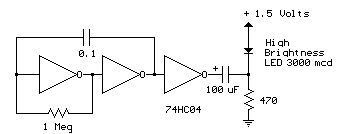
Several 1.5 V LED flasher circuits can be found online, and four of them are presented here. The flasher circuits operate on a single 1.5 V power supply. The design of a 1.5 V LED flasher circuit typically involves a...

This is a low-power voltmeter circuit designed for use with alternative energy systems operating on 12V and 24V batteries. The voltmeter features an expanded scale that displays small voltage increments within the 10 to 16V range for 12V batteries...

Five pins RA0 to RA4 are used as inputs. The pins are connected to the 5V average resistance 10K (Pull-up). So when no switch is not depressed all the pins have a high potential (HI +5 V). When one...

A detailed DIY remote-controlled AC fan regulator with 10-stage speed control. It is built using the ATmega8 microcontroller, and includes full source code and PCB layout. This project involves designing a remote-controlled AC fan regulator that allows users to adjust...
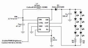
The schematic diagrams for the TPS61042 current LED driver illustrate its capability to power eight LEDs with an efficiency of 81% at 3.6V and 18.6mA. The TPS61042 is commonly utilized in applications such as white LED supply for backlight...
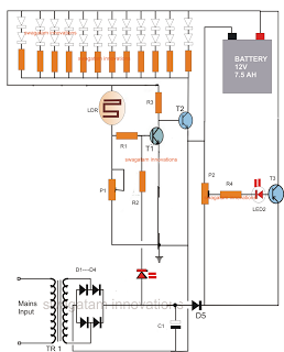
The following circuit is an LED emergency light circuit featuring advanced functionalities such as overcharge battery cut-off, daytime auto-disable, and automatic activation of the LEDs during AC mains failure, reverting to charging mode when power is restored. The circuit...