
Infrared Remote Control Tester Circuit

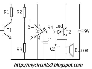
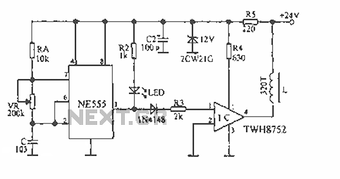
This infrared remote control tester circuit is designed to verify the functionality of infrared remote controls commonly used with various electronic devices. The primary components of the circuit include a photodiode or phototransistor, which detects infrared signals emitted by the remote control, and a simple LED indicator that lights up when an infrared signal is detected.
The circuit operates by placing the photodiode or phototransistor in close proximity to the infrared remote control. When a button on the remote is pressed, it emits infrared light, which is picked up by the photodiode or phototransistor. The output from the photodiode or phototransistor is then fed into a resistor and connected to an LED. The LED illuminates in response to the detected infrared signal, providing a visual indication that the remote is functioning properly.
To construct this circuit, the following components are typically required:
- A photodiode or phototransistor (such as a TSOP series receiver)
- An LED (light-emitting diode)
- A resistor (typically in the range of 220 to 1k ohms)
- A power supply (such as a 9V battery)
- A breadboard or PCB for assembly
The circuit can be easily assembled on a breadboard for prototyping. The photodiode or phototransistor should be oriented to face the infrared source, while the LED should be connected in such a way that it illuminates when the photodiode or phototransistor receives sufficient infrared light. Proper orientation and alignment are crucial for accurate testing.
This simple yet effective circuit serves as a valuable tool for troubleshooting and verifying the operation of infrared remote controls, making it an essential project for electronics enthusiasts and professionals alike.Infrared Remote Control Tester Circuit This is a simple circuit you can build in order to test infrared remote controls. The circuit uses an.. 🔗 External reference
Related Circuits
There are digital and analog methods that can be used to compensate for the nonlinearity of a PT100 RTD. Digital linearization can be implemented through various techniques. Compensation for the nonlinearity of a PT100 RTD (Resistance Temperature Detector) is essential...
The drawback of the circuit mentioned is that the operational amplifier (op-amp) supply is connected to the high voltage (HV) supply. Most op-amps are limited to approximately 30V for their supply voltage, which prevents the circuit from functioning with...
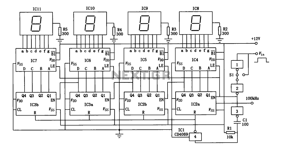
A digital pulse width measurement circuit is presented. It operates with a 100 kHz reference frequency to count the pulse width of the input signal. The count value represents the measured pulse width displayed on four seven-segment LED displays....
This circuit activates an alarm whenever an object crosses the laser beam emitted by a laser. The output of the IC TL071 goes high when the laser beam is interrupted. This output voltage is further amplified by an NPN...
The device is designed to accelerate the defrosting process of fish, meat, and other foods by utilizing audio vibrations. This method allows for defrosting in warm water, significantly reducing the time required compared to conventional methods, while preserving the...
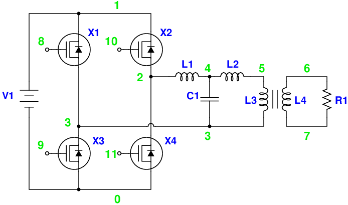
Magic Sinewave Analysis using SPICE and a Simple Inverter Circuit. This document discusses the analysis of a sinewave signal generated by a simple inverter circuit using SPICE simulation software. The inverter circuit is designed to convert a DC input voltage...