
Practical Data Acquisition using a Windows based Power Meter
The design of the PC-based, 14-bit data acquisition system is an intricate amalgamation of various electronic components and methodologies aimed at achieving high precision and reliability in measurements. The system utilizes a precision resistive divider, specifically the ORNA10-1 resistor network, which is instrumental in ensuring accurate voltage measurements. This network's configuration allows for a high degree of ratiometric accuracy, critical for applications requiring precise voltage readings.
The choice of the MAX125 ADC is significant due to its fault-protected input, which is essential for safeguarding the system during operation. This feature not only enhances the safety of the device under test but also provides a robust framework for measuring both input and output voltages without compromising the integrity of the data. The integration of the MAX471 current amplifier further complements the design by enabling accurate current measurements, which are crucial for evaluating the performance of DC-DC converters.
The use of the RS-232 interface for data transmission is a practical choice, allowing for straightforward communication between the data acquisition system and the PC. This interface facilitates the transfer of digitized results to the PC, where they can be processed and displayed in real-time. The update rate of once per second aligns with standard multimeter operations, ensuring that users receive timely and relevant data.
Buffering the inputs with the MAX4254 op-amp is a strategic decision that mitigates the challenges associated with low input impedance. This buffering not only enhances the accuracy of the measurements but also improves the overall performance of the ADC by ensuring that the sample/hold capacitor is charged efficiently. The design's attention to detail, such as the consideration of RC time constants, reflects a thorough understanding of the requirements necessary for achieving high-performance data acquisition in various applications.
Overall, the application note provides a comprehensive overview of the design, implementation, and operational considerations of a PC-based, 14-bit data acquisition system, serving as a valuable resource for engineers and developers in the field.This application note describes the design of a PC-based, 14-bit data acquisition system. It takes a system approach, includes all the necessary building blocks: analog, digital, hardware, and software. It discusses each step, testing systems separately before integrating them, and detailing pitfalls learned along the way.
Many articles h ave been written about the building blocks in a typical data acquisition system, but few address the entire system, from analog input to PC display. To cover all the problems encountered in designing a complete data acquisition system, the engineer might have to amass ten articles.
The following application note describes the design of a PC-based, 14-bit data acquisition system. It takes a system approach, includes all the necessary building blocks: analog, digital, hardware, and software. It discusses each step, testing systems separately before integrating them, and detailing pitfalls learned along the way.
The need for a power meter is apparent to anyone who has tried measuring the input and output characteristics of a DC-DC converter using conventional instruments. The design allows users to perform load measurements on the device under test without connecting an endless spaghetti-mass of test leads.
Figure 1 shows the completed power meter display on a personal computer (PC) monitor. To cater for boost, buck, and linear implementations, the measurement range was chosen as 30V for both input and output. Most quality DC-DC converters operate at 100kHz or higher. The system`s frequency response should therefore be higher than 100kHz, but a slower response is also acceptable because the switching waveforms are reasonably repetitive.
The system`s 14-bit resolution was not of prime importance in the design stage, because measurements to within 0. 1% (10 bits) are perfectly adequate for most power-meter applications. Once digitized, the results are uploaded via an RS-232 interface and displayed on a PC screen, with an update rate of once per second (like most multimeters).
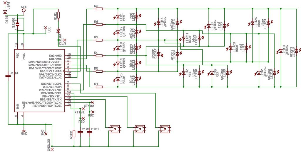
Once data arrives at the RS-232 port, the power of the PC can be unleashed upon it. The full circuit diagram (Figure 2) will be discussed in sections: A precision resistive divider allows accurate voltage measurements up to 30V. The ORNA10-1 from Vishay Thin Film is a trimmed resistor network comprising two 1k © and two 10k © values.
The ratiometric accuracy of these four resistors is 0. 05%, and so provides a precision fraction (1/11) of the applied voltage. The MAX125`s fault-protected input has a range of ±5V, which allows a degree of safety under fault conditions and plenty of headroom for input and output voltage measurements. Input and output currents are measured using the precision current amplifier MAX471. This device measures the voltage across an internal 30m © resistor, and delivers an output current whose amplitude equals 500uA per ampere of high-side current.
Thus, the value of an external resistor scales the output voltage, and suitable resolution is achieved in this case by selecting a value of 4. 7k ©. The MAX125`s wide input capability and fault-protection circuitry give it a lower input impedance than that of equivalent competitive devices, so the four readings are buffered before entering the ADC.
Unity-gain buffer stages are taken from the MAX4254 quad precision op amp, whose input offset voltages (70uV) are lower than the system resolution. The MAX125 inputs are buffered mainly to overcome their low input impedance, but driving an ADC from low impedance is always good practice even when the converter has a high input impedance.
Because sample/hold circuitry is normally placed right at the ADC input, the buffer provides the necessary drive for charging the sample/hold capacitor in an acceptable time. To get an idea of how low the source impedance has to be, consider a simple calculation of RC time constant.
The input capacitor charges 🔗 External reference
Related Circuits
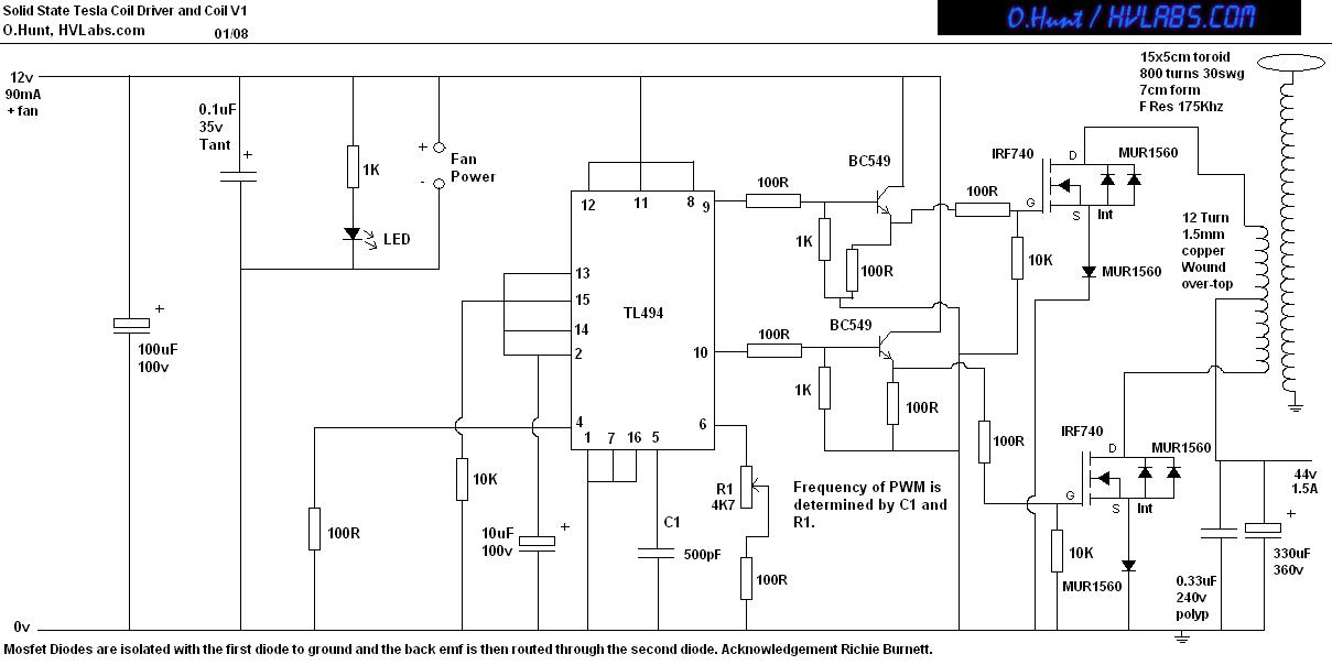
This is a solid-state version of a Tesla coil, replacing the spark gap with MOSFET transistors and utilizing a close-coupled primary coil without capacitors. The method of driving the primary coil varies among designs. After researching various works online,...
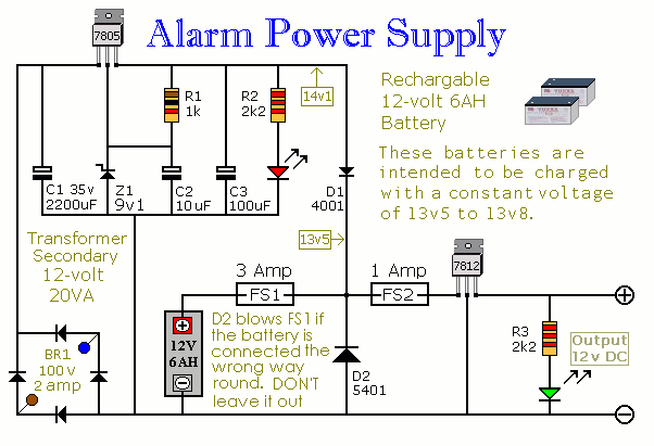
This Power Supply is suitable for the Modular Burglar Alarm. However, it has other applications. It is designed to provide an output of 12-volts, with a current of up to 1-amp. In the event of mains failure, the back-up...
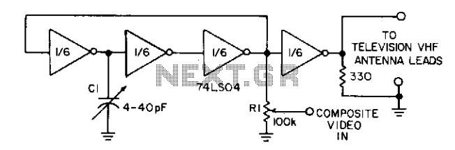
Three gates of a 74LS04 form the oscillator circuit. Capacitor C1 allows fine frequency adjustment to a specific television channel and helps stabilize the circuit. Potentiometer R1 acts as the mixing input and provides adjustment of the contrast ratio...
Microdot - wrist watch LED pattern timepiece. This project is a circuit board designed for creating a wristwatch-sized version. The Microdot wristwatch project involves the design and implementation of a compact circuit board that integrates LED technology to display time...
This AC to DC power supply can output 5A in continuous operation and 12A peak current. This type of DC power supply utilizes a PCB, allowing for the use of two case types. The described AC to DC power supply...
When this thermometer is utilized in a room environment, it operates intermittently, maintaining this operational state within the temperature measurement circuit due to the stable internal temperature. The astable multiresonance oscillator is composed of transistors VT1 and VT2, forming...
Warning: include(partials/cookie-banner.php): Failed to open stream: Permission denied in /var/www/html/nextgr/view-circuit.php on line 713
Warning: include(): Failed opening 'partials/cookie-banner.php' for inclusion (include_path='.:/usr/share/php') in /var/www/html/nextgr/view-circuit.php on line 713