
preamp
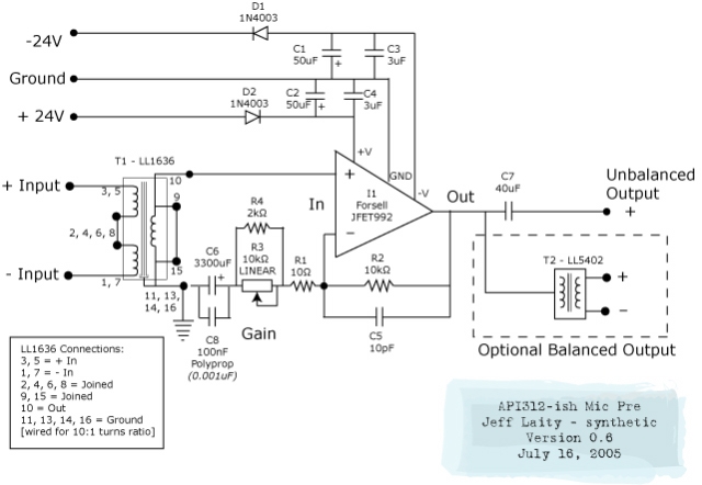
The microphone preamplifier schematic serves as a crucial component in audio signal processing, amplifying low-level signals from microphones to a usable level. The design typically includes an input stage, gain control, and output stage. The input phase switch allows for the inversion of the signal phase, which can be useful for correcting phase issues in multi-microphone setups.
The phantom power circuit, while not depicted in the schematic, is essential for powering condenser microphones that require external voltage. This circuit typically provides +48V DC through balanced XLR connectors, ensuring compatibility with a wide range of professional microphones.
Incorporating the Jensen AS016 design principles, this schematic emphasizes low noise and high fidelity. The use of high-quality components is recommended to maintain signal integrity. The gain stage may utilize operational amplifiers configured for optimal performance, ensuring minimal distortion and a broad frequency response.
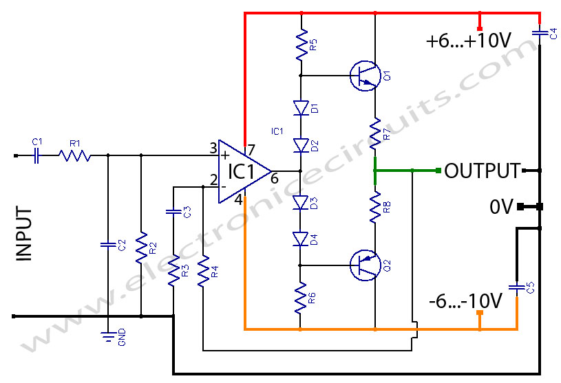
Overall, this microphone preamp design is intended for professional audio applications, providing a solid foundation for high-quality recordings. Proper implementation of the input phase switch and phantom power circuit will enhance its functionality, making it suitable for various recording environments.Here`s my final mic pre schematic. The input phase switch and phantom power circuit is not shown, but is based on Jensen mic input design AS016. Click here for the discussion thread on this project. 🔗 External reference
Related Circuits
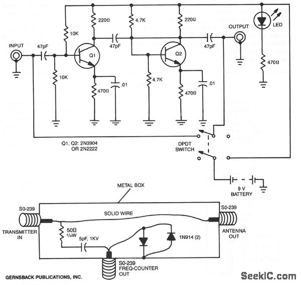
By utilizing a preamplifier with a short length of shielded cable and clip leads, signals that typically do not produce a readout can generate precise and stable readouts on the counter. A DPDT switch is incorporated to bypass the...
The sound card for a PC generally has a microphone input, speaker output and sometimes line inputs and outputs. The mic input is designed for dynamic microphones only in impedance range of 200 to 600 ohms. Lazar has adapted the...
This preamplifier is designed for low-resistance sources such as moving coil heads (MC). The circuit employs three parallel double transistors, SSM2220 or MAT03, which form a differential amplifier that minimizes noise. When connected to an OP27 amplifier, it further...
The amplifier drives a pair of loudspeakers using two LM3876 integrated power amp ICs (50 watts per channel), or a pair of headphones via a Meier crossfeed filter and an OPA2134 dual opamp. It provides four switchable line level...
Headphone Amplifier or Pre-Amplifier Output Stage. This 1-watt amplifier is ideally suited for use as a driver for low-impedance headphones. The headphone amplifier circuit is designed to provide an amplified audio signal to drive low-impedance headphones effectively. Operating at a...
The circuit is based on a single operational amplifier integrated circuit designed to produce a modular preamplifier that operates in Class A configuration. The modular preamplifier circuit utilizes a single operational amplifier (op-amp) integrated circuit, which serves as the primary...