
Precision digital timing controller circuit (CC4013, CC440, CC4060, G1555)
The precision digital timing control circuit operates through a well-coordinated arrangement of components designed to achieve accurate timing intervals. The core of the system is the crystal oscillator, which generates a stable frequency that is crucial for timing accuracy. The 32,768 Hz watch crystal is specifically chosen for its reliability and precision in timekeeping applications. The series of binary counters provides the necessary division of frequency, allowing for the generation of various timing intervals.
The dual D flip-flop (IC3) serves a critical role in further dividing the frequency, ensuring that the output is suitable for the subsequent timing logic. The CC4040 counter (IC4) is versatile, with multiple output stages that allow for a range of timing options. Each output pin corresponds to a specific timing interval, which can be selected using the switch K, making the circuit adaptable to various timing requirements.
The use of transistors (BG1 and BG2) as amplifiers ensures that the signals are strong enough to drive the relay, which is essential for controlling larger loads. The 555 timer is employed in a monostable configuration, providing a reliable mechanism for activating and deactivating the relay based on the timing intervals set by the user.
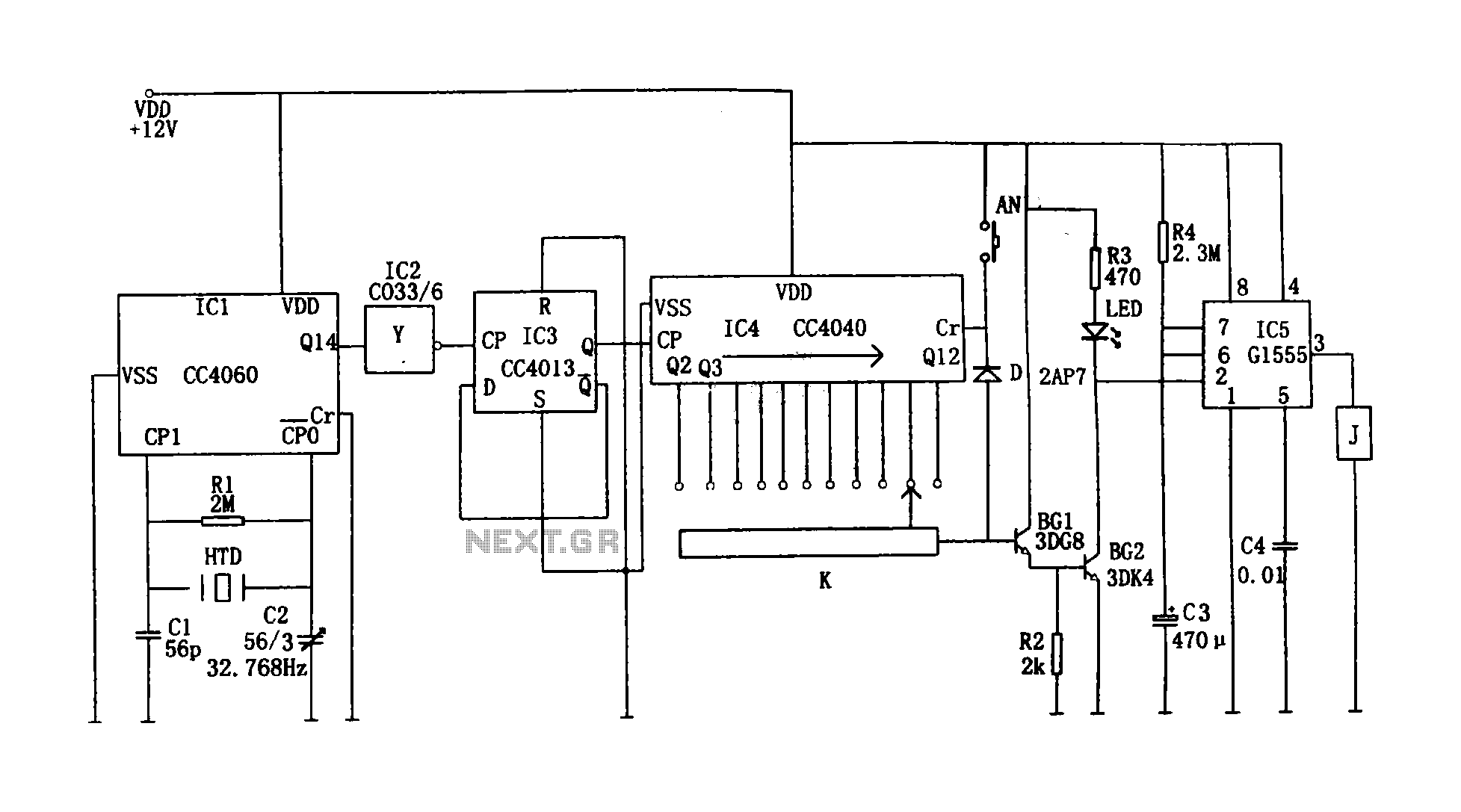
The circuit's design facilitates a straightforward operation: after a predetermined delay, the relay engages, powering the load, and subsequently disengages after the set timing period. This functionality is particularly useful in applications requiring precise control over timing, such as in automation systems, lighting control, and other electronic applications where timing is critical. The ability to reset the timer and start a new cycle enhances the circuit's usability, allowing for repeated operations without manual intervention. Overall, the precision digital timing control circuit exemplifies an effective integration of various electronic components to achieve a highly functional timing solution.Shown for the precision digital timing control circuit. The controller consists of crystal oscillator circuit, a divider, counting circuit, monostable flip-flops. Crystal oscillator circuit consists of 14 serial binary counter / divider, watch crystal (32768Hz), C1, C2 and so on. Oscillator signal after 214 division (Q14) output from the pin, inverted by the IC2, then after the double-D flip-flop CC4013 (IC3) divided by two to give the signal of 1Hz, the signal is applied to the CP end of IC4, as a clock control signal.IC4 is a 12-bit serial binary counter / divider CC4040, when the CP signal at a frequency of 1Hz, 11 output terminals Q4 ~ Q9, Q12 ~ Q14 respectively output 2 seconds, 4 seconds, 8 seconds, 16 seconds, 32 seconds , 64 seconds, 128 seconds, 256 seconds, 512 seconds, 1024 seconds, 2048 seconds pulse (high step).
Based on the timing required by sub-line single-pole 11 throw switch K corresponding step level timing leads the way. Added to the amplifier BG1, BG2, by the amplified signal coupled to IC5 feet, 555 feet low because occurs set, pin output high relay J pull, turn the corresponding control load, so that the work load.The timing controller work program is: Wait 2N (N = 2 ~ 11) seconds after the relay only pull, turn the work.
After that, because C3 is charged through R4, when the voltage on C3 charge to make potential reaches 6 feet 2 / 3VDD, the 555 reset occurs, the output pin low relay J release, the corresponding load off, stop working. At the same time, a signal from the K leads through diode D after clearing Cr added to the end of IC4 (12 feet), the timer is cleared, that is, in 555 output is high, the load is turned on at the same time, and from 0 to start counting , the timing of the next round.
Thus achieving different general timer.Timing of the timing controller can be from 2 to 2,048 seconds, minutes, 11-grade, high timing accuracy, than the average over the timer.
Related Circuits
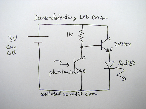
The following circuit illustrates a simple and inexpensive dark-detecting LED circuit. Features include the use of photoresistors, specifically a photocell or LDR, and an LED. This circuit utilizes a light-dependent resistor (LDR) as the primary sensing element. The LDR exhibits...
The PowerSaver Flasher uses capacitive output coupling to produce brighter shorter flashes and has a much lower average current drain than standard bicore or 74HC14 flashers. The PS Flasher with one LED circuit (2 LEDs) runs all night from...
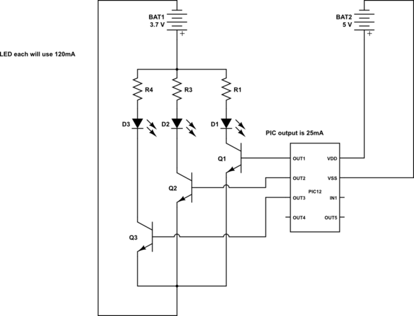
This is a conceptual schema utilizing a PIC12 microcontroller to control the blinking of three LEDs, each exhibiting different blinking patterns. There are several questions that need to be addressed. The circuit design involves a PIC12 microcontroller, which is a...
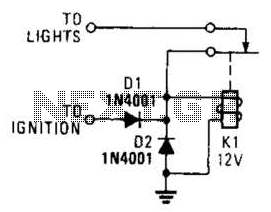
A relay and two diodes are all that is needed; the relay performs the job of a buzzer, so no annunciator is required. When the lights are left on while the ignition is off, the normally closed relay contacts...
This is a simple 50 MHz auto-ranging frequency meter developed as a course project by Simone Benvenuti and Andrea Geniola. It utilizes a single PIC 16C84 microcontroller and four displays to measure frequencies in the range of 0 Hz...
This sound effects circuit is designed to function as a signal distorter. When utilized with an electric guitar, it enables the creation of unique sound effects. The sound effects circuit operates by manipulating the input audio signal from the electric...
Warning: include(partials/cookie-banner.php): Failed to open stream: Permission denied in /var/www/html/nextgr/view-circuit.php on line 713
Warning: include(): Failed opening 'partials/cookie-banner.php' for inclusion (include_path='.:/usr/share/php') in /var/www/html/nextgr/view-circuit.php on line 713