
Precision LED Blinker
The circuit operates by providing a stable and adjustable drive current to the LED, ensuring consistent performance during operation. The adjustable regulated current source utilizes an operational amplifier (op amp) in conjunction with a transistor (Q2) to maintain a constant current output, which is crucial for applications requiring precision in light output. The differential amplifier formed by transistors Q3 and Q4 acts as a switch, controlling the flow of current to the LED based on the TTL input signal. This configuration allows for rapid switching of the LED, achieving rise and fall times of less than 500 nanoseconds, which is essential for high-speed applications.
The level shifter (Q1) is implemented to convert the TTL signal levels to those compatible with the differential amplifier, ensuring that the circuit can effectively respond to digital signals. This integration of components allows the circuit to be versatile, making it suitable not only for biological experiments but also for industrial applications such as turbidity and densitometry measurements, where precise light modulation is required.
Overall, this circuit design emphasizes low-cost and readily available components, making it accessible for various experimental and practical applications. The careful selection of components and their configuration ensures that the circuit meets the demands of high-speed switching and stable light output, contributing to its effectiveness in both research and practical implementations.The circuit allows a precision regulated drive current to be set to drive an LED, and in response to a TTL level signal, the LED is switched on and off with rise and fall times of less than 500 nanoseconds and less than 7% overshoot. This was designed for biological experiments to study the photo repsonse of cone cells rabbit eyes. This circuit may also be useful in systems that require a stable pulsed light source, such as those that measures light transmission (turbidity and densitomitry insturments, for example) and for the transmission of low speed optical data (to 200 kHz).
The components are all easy to obtain and low cost. The circuit consists of an adjustable regulated current source (the op amp and Q2), a differential amplifier (Q3 and Q4) driven as a switch, and a level shifter (Q1) to shift the TTL input signal to levels necessary to drive the differential pair. The current from the current source is switched to either the +5 volt supply to the LED by the differential amplifier.
🔗 External reference
Related Circuits
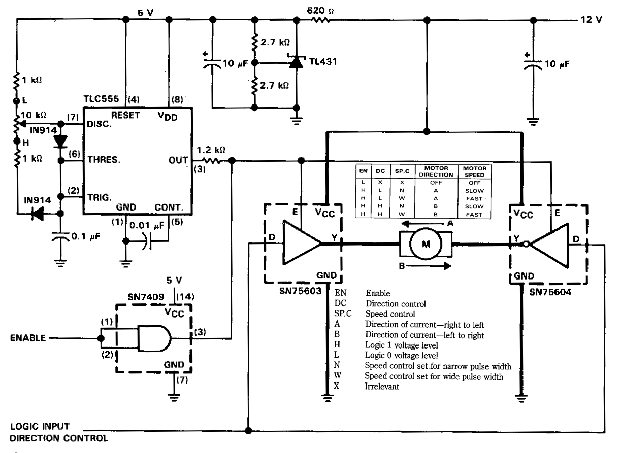
The figure illustrates a reversible DC motor drive application with adjustable speed control. The D inputs for these drivers are complementary and can be tied together and driven from the same logic control for bidirectional motor drive. The enables...
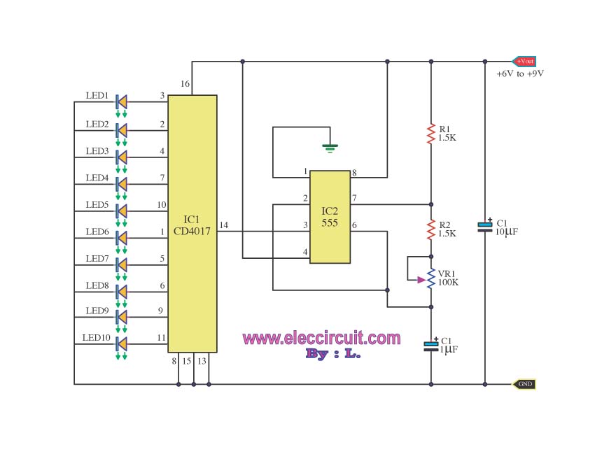
For constructing a 10 LED Chaser circuit, it is recommended to start with this design. It utilizes the widely used and cost-effective IC-4017 decade counter. The 10 LED Chaser circuit is an engaging project that demonstrates the sequential lighting of...
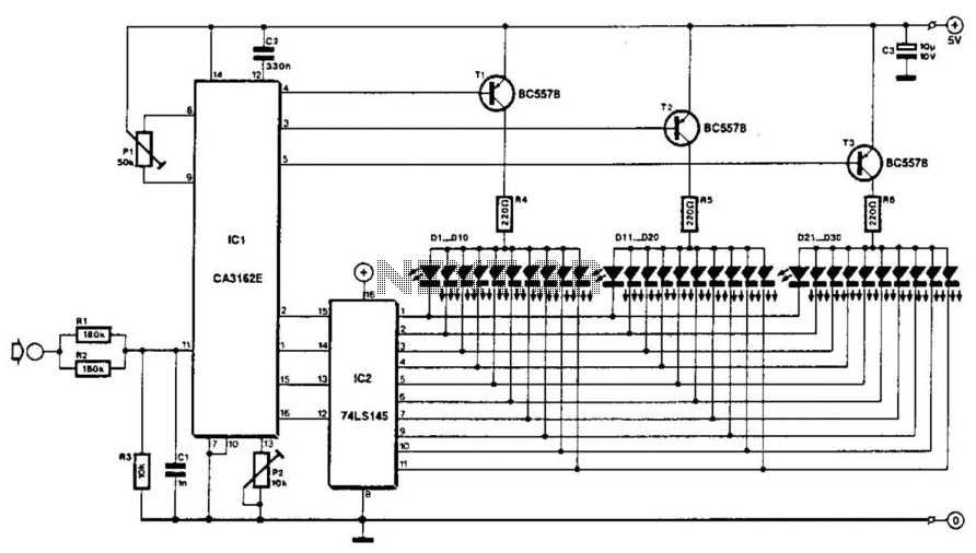
The voltage to be measured is digitized in an analog-to-digital (A/D) converter and then displayed in three decimal digits. The display consists of three groups of 10 LEDs. The meter can only be used for measuring direct voltages. The...

This circuit is a voltage-controlled oscillator (VCO) that utilizes the 555 timer integrated circuit (IC) as its primary component. The 555 timer is configured as an astable multivibrator, enabling it to function as an oscillator. An astable multivibrator is...
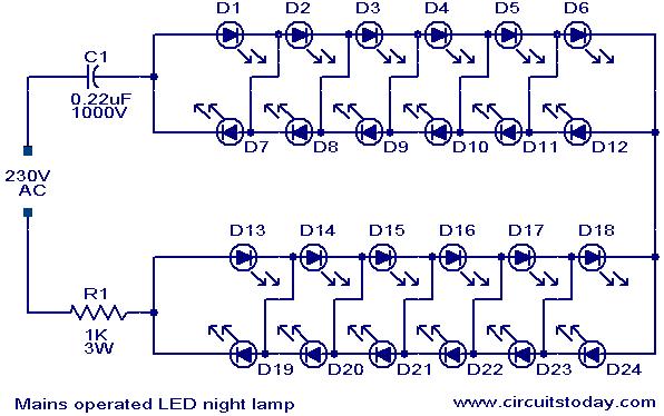
A simple and effective LED-based night lamp circuit is designed to operate directly from the 230V mains supply. The circuit utilizes a total of 24 white LEDs, producing an output of approximately 15W. Current limiting is achieved through resistor...
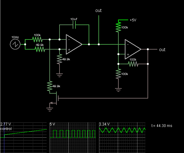
This circuit is a voltage-controlled oscillator, which is an oscillator whose frequency is determined by a control voltage. A 10 Hz sawtooth oscillator provides the control voltage in this case; this causes the frequency to rise slowly until it...
Warning: include(partials/cookie-banner.php): Failed to open stream: Permission denied in /var/www/html/nextgr/view-circuit.php on line 713
Warning: include(): Failed opening 'partials/cookie-banner.php' for inclusion (include_path='.:/usr/share/php') in /var/www/html/nextgr/view-circuit.php on line 713