
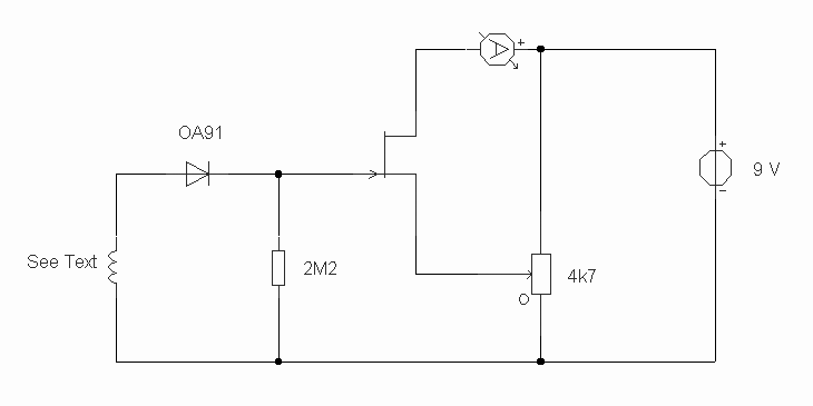
Precision photodiode level detector
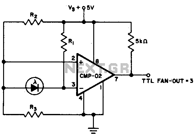
The described circuit likely involves a photodiode used in conjunction with resistors R1, R2, and R3 to create a voltage divider or a similar configuration that influences the output state based on the current generated by the photodiode. When light strikes the photodiode, it generates a current that varies with the intensity of the light. The critical point mentioned is when this current reaches 0 µA, indicating a threshold at which the output state transitions.
In this configuration, R1, with a resistance of 2 MΩ, may serve as a load resistor for the photodiode. The values of R2 and R3, both at 5 MΩ, suggest they could be configured as pull-up or pull-down resistors, or they might be part of a feedback loop in an operational amplifier setup.
The output state change at 0 µA indicates that the circuit is designed to detect the absence of light or a very low light condition. This output could be used in various applications such as light-sensing alarms, automatic lighting systems, or in optical communication systems where the presence or absence of light signals a state change.
The overall performance of this circuit will depend on the characteristics of the photodiode, including its responsivity and the wavelength of light it is designed to detect, as well as the power supply and any additional components that may be included in the circuit for signal conditioning or amplification. Proper selection and placement of components will ensure that the circuit operates effectively at the specified thresholds and provides reliable output states in response to varying light conditions.The output state changes at a photo diode current of 0 µA For Rl = 2 M, R2 = R3 = 5 M. 🔗 External reference
Related Circuits
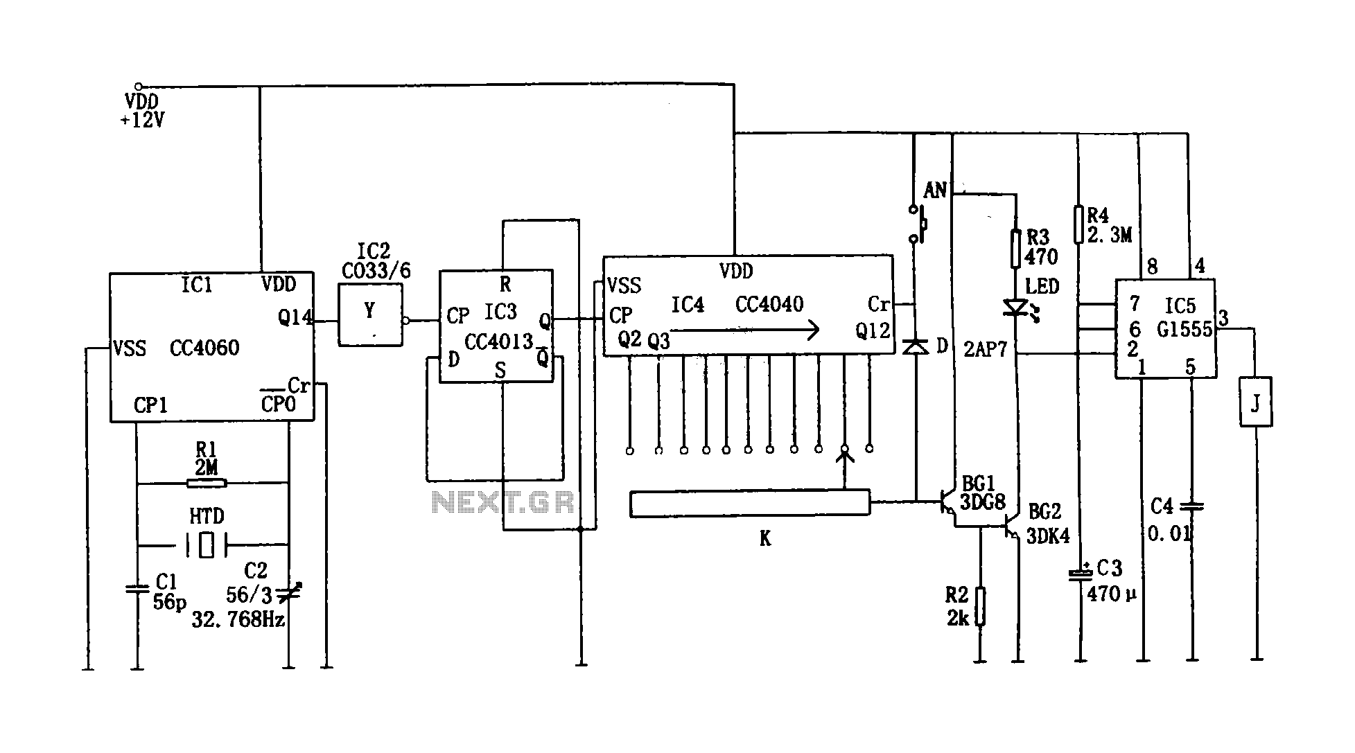
This circuit illustrates a precision digital timing control system. The controller includes a crystal oscillator circuit, a divider, a counting circuit, and monostable flip-flops. The crystal oscillator circuit features a series of 14 binary counters/dividers, a watch crystal operating...
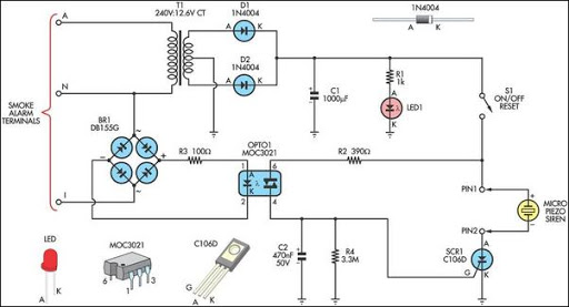
This alarm circuit is designed to monitor a mains-powered smoke detector located in a shed used for dog kennels. It ensures complete isolation from the mains, allowing low-voltage (12V) cabling to run to the alarm circuit, which is situated...
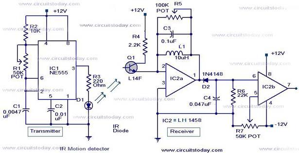
Infrared (IR) Motion Detector Circuit featuring a motion detector alarm and an infrared sensor. The circuit diagram and its operation are provided in detail. The infrared (IR) motion detector circuit is designed to detect motion within a specified range and...

When the water level is low, the wires in the tank are open-circuited, causing the 180K ohm resistor to pull the switch low, resulting in the switch being open and the LEDs being off. As water begins to fill...
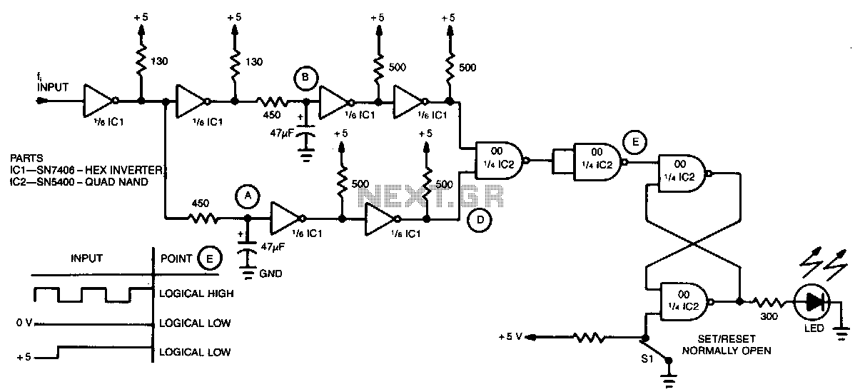
A simple inverter and NAND gate can be connected to create a highly compact and reliable digital frequency detector. This circuit is capable of detecting frequencies up to 3 MHz with a 50% duty cycle. When a frequency appears...
The circuit was constructed using a few components powered by a 9 V battery for sensing the presence of bugs transmitting within the frequency modulation range. Frequency Modulation (FM) transmits its signal or information over a carrier wave by...
Warning: include(partials/cookie-banner.php): Failed to open stream: Permission denied in /var/www/html/nextgr/view-circuit.php on line 713
Warning: include(): Failed opening 'partials/cookie-banner.php' for inclusion (include_path='.:/usr/share/php') in /var/www/html/nextgr/view-circuit.php on line 713