
dc motor control circuit

The circuit utilizes two normally open push-button switches, S1 and S2, which allow for user interaction to control the motor's operation. The momentary action of these switches means that the motor will operate only while the buttons are pressed, providing a simple and effective way to manage the opening and closing of curtains.
The inclusion of diodes, which can be either red or green, serves a dual purpose. Primarily, they indicate the direction of the motor's rotation, enhancing user feedback during operation. The choice of diodes may also reflect aesthetic preferences or design requirements.
The TIP31 transistors in the circuit act as switches that control the motor's power based on the signals received from the push-button switches. It is crucial to select transistors that can handle the current requirements of the motor. The circuit should be designed with consideration for the load conditions, as running the motor under load will increase the current draw, which may necessitate the use of transistors with higher current ratings.
The four diodes positioned around the motor are essential for protecting the circuit from back electromotive force (back EMF) generated when the motor is turned off. This back EMF can potentially damage other components in the circuit, and thus, the selection of appropriate diodes is critical. For a 12V motor with a current draw of 1 amp under load, the use of 1N4001 diodes is suitable due to their voltage and current ratings.
Overall, this circuit design provides a practical solution for controlling the light entering a room through curtains, offering users the ability to adjust the opening based on their preferences while ensuring the longevity and reliability of the electronic components involved.Here, S1 and S2 are normally open, push to close, press button switches. The diodes can be red or green and are there only to indicate direction. You may need to alter the TIP31 transistors depending on the motor being used. Remember, running under load draws more current. This circuit was built to operate a small motor used for opening and closi ng a pair of curtains. As an advantage over automatic closing and opening systems, you have control of how much, or how little light to let into a room. The four diodes surriunding the motor, are back EMF diodes. They are chosen to suit the motor. For a 12V motor drawing 1amp under load, I use 1N4001 diodes. 🔗 External reference
Related Circuits

This remarkably straightforward circuit enables the operation of one or two robust 12V 21W car bulbs in a flashing mode using a power MOSFET. Such devices are especially suitable for road, traffic, and yard alerts, as well as in...
This amplifier is designed to be self-contained within a compact loudspeaker enclosure. It can be powered by devices such as Walkmans, Mini Discs, iPods, CD players, computers, and other devices equipped with line or headphone outputs. Typically, two units...

A bass player setup utilizing a stereo control is implemented through an LM1877 amplifier circuit. A cermet stereo microphone pickup is used to capture audio signals from a stereo turntable, with left and right channel outputs. The audio signals...

It utilizes the SHD series of electronic control equipment modules. The fan control box KZH functions as the HKD 1F electronic module. The SHD series of electronic control equipment is designed for various applications, including fan control systems. Within this...
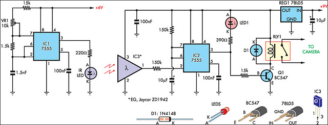
This circuit serves as an alternative to the infrared (IR) beam break detector featured in the June 2009 issue of Silicon Chip. To enhance its insensitivity to ambient light, it employs a standard IR receiver integrated circuit (IC), such...

Maxim has introduced a series of five integrated oscillator building blocks in the MAX260x series, covering a frequency range of 45 to 650 MHz. The MAX2606 is designed for the VHF band, allowing frequency variation of approximately ±3 MHz...