
Digital displaying photoelectric counter circuit diagram
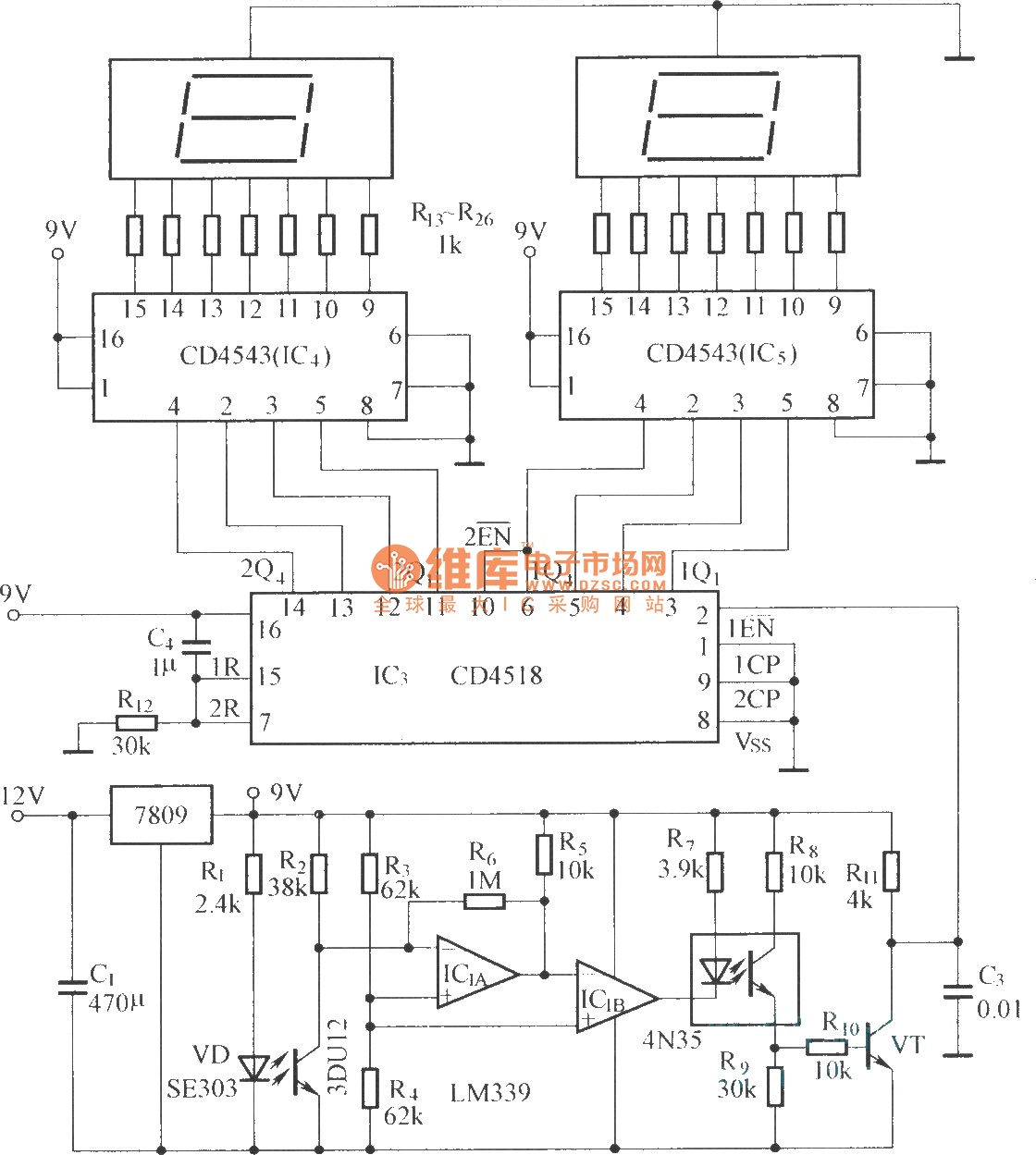
The circuit architecture consists of several key components that work together to process optical signals and convert them into a readable format. The optical input circuit, utilizing a photodiode (VD, 3DU12), is responsible for detecting incoming light signals. This photodiode generates a small current in response to incident light, which is then fed into the pulse forming circuit.
The pulse forming circuit is crucial for shaping the detected signals into a format suitable for further processing. It employs operational amplifiers IC1A and IC1B configured as a voltage comparator. This configuration allows for the detection of specific voltage levels, which corresponds to the presence or absence of optical signals. The output of the comparators is then sent to an optical coupler, which serves to isolate different sections of the circuit while allowing the signal to pass through.
Following this, a transistor switching circuit is implemented to control the flow of current based on the output from the optical coupler. This switching action is essential for driving the subsequent components of the circuit, ensuring that the detected signals can effectively trigger the counting and display circuit.
The counting and display circuit is designed to count the number of pulses generated by the pulse forming circuit and present this information visually. This component typically includes a microcontroller or a digital counter IC that processes the input signals and drives a display, such as an LED or LCD, to show the count. The integration of these components allows for real-time monitoring and visualization of the optical signals, making the circuit suitable for various applications in optical communication and signal processing.The circuit has optical input circuit (VD, 3DU12), pulse forming circuit (IC1A, IC1B form the voltage comparator; optical coupler; transistor switching circuit) and counting and display circuit.. 🔗 External reference
Related Circuits
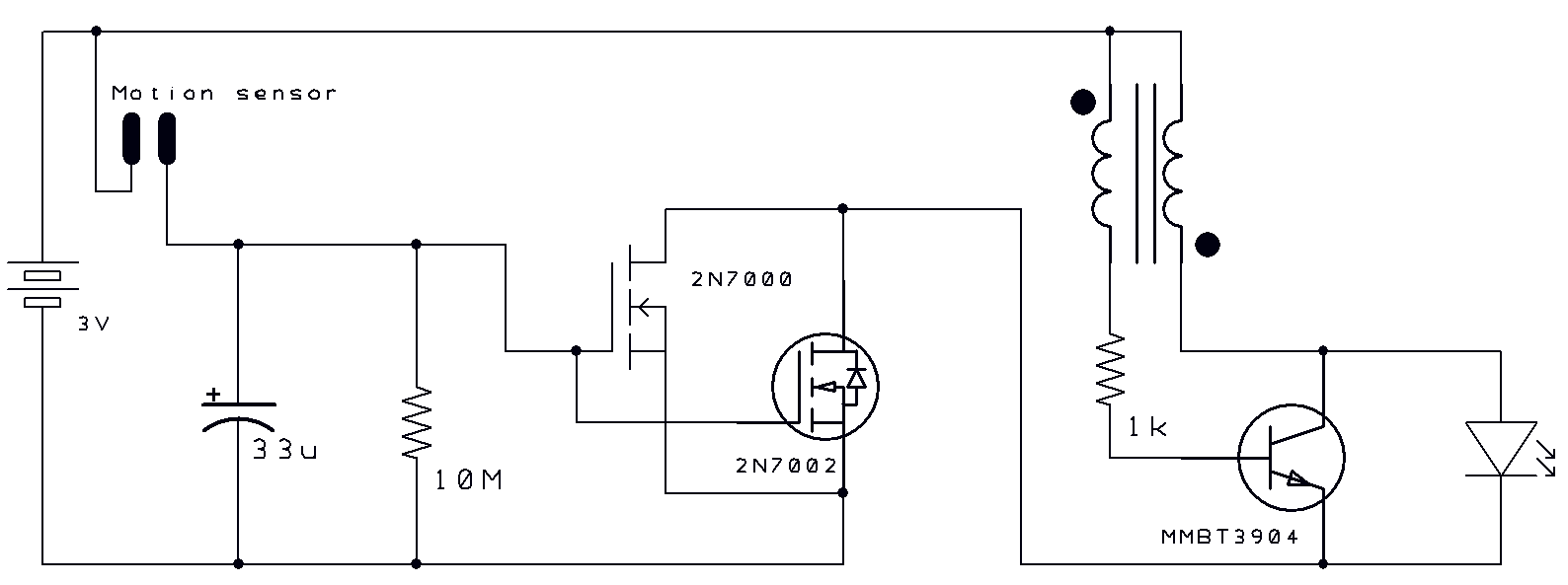
Two thoughts on a motion-activated Joule Thief LED bike light. The circuit for switching on and delayed switch-off is simple. The motion-activated Joule Thief LED bike light utilizes a straightforward circuit design that capitalizes on the principles of energy conservation...
The receiver is based on a basic SA612 circuit. The local oscillator (LO) for the 20-meter band operates at approximately 9 MHz, with an intermediate frequency (IF) of 5.068 MHz. The IF filter employs two crystals and has a...
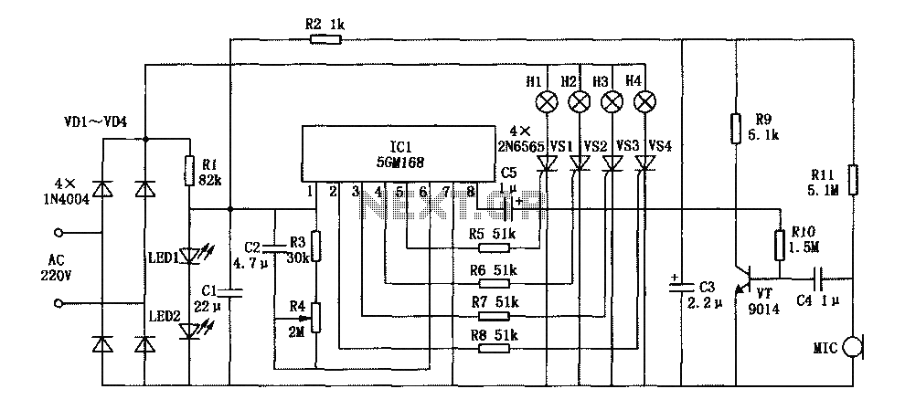
This document describes a family karaoke lighting design that employs various methods to control the circuit. The control circuit presented here features a four-way light output with loop jumping and speed control capabilities. The practical circuit utilizes a microphone...
A car inverter, also known as a power converter or power inverter, is a device that converts 12V DC from a vehicle’s electrical system into 220V AC for general electrical use. It serves as a convenient power adapter for...
The use of diode rectifiers in AC voltmeters with a low lower limit of measurement range (0.5-1 V) leads to significant nonlinearity of the scale due to the nonlinearity of the current-voltage characteristics of diodes. The incorporation of electronic...
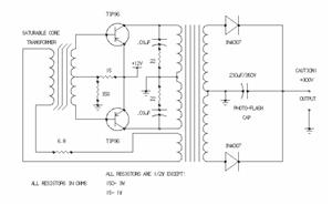
The two unspecified polarized capacitors (one directly above the transformer and one directly to the right of the transformer) are actually each a pair of 470 µF capacitors in parallel (for a total of four 470 µF capacitors). These...