
Pro Maniac Guitar tube power amplifier II
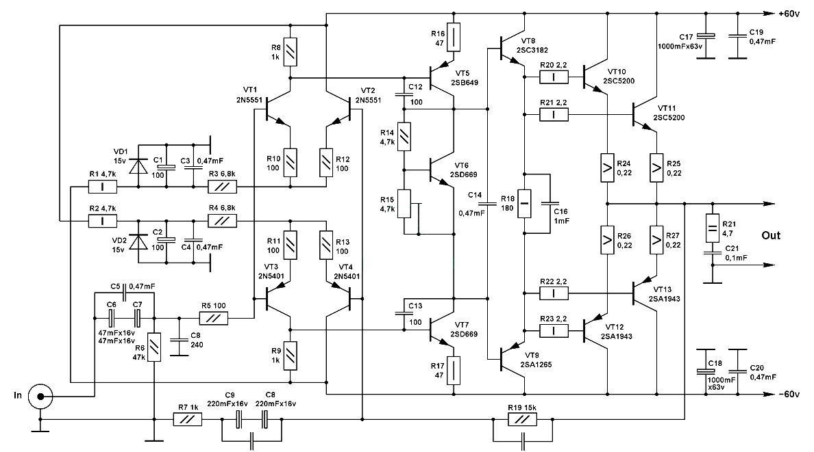
The improved version of the Pro Maniac Guitar tube power amplifier features several enhancements aimed at increasing performance, reliability, and sound quality. The schematic typically includes a power supply section that provides the necessary voltage and current to the amplifier circuit. This section may utilize a transformer to step down the mains voltage, followed by a rectifier circuit to convert AC to DC, and filter capacitors to smooth the output.
The amplifier stage is likely based on vacuum tubes, which are known for their warm sound characteristics. The tube configuration may include a combination of preamp and power tubes, arranged in a push-pull configuration to maximize output power while minimizing distortion. The choice of tubes, such as 12AX7 for the preamp stage and EL34 or 6L6 for the output stage, contributes significantly to the tonal quality of the amplifier.
Signal paths in the schematic are designed to minimize noise and interference, often employing shielded wiring and careful grounding techniques. The use of high-quality components, such as resistors and capacitors, further enhances the overall performance. The tone control section may include potentiometers for adjusting bass, midrange, and treble frequencies, allowing users to shape their sound to personal preference.
Feedback loops may be implemented to stabilize gain and reduce distortion, while output transformers are used to match the impedance of the tubes to the speaker load, ensuring efficient power transfer. The schematic may also include protection features, such as fuses or circuit breakers, to prevent damage from overload conditions.
In summary, the improved Pro Maniac Guitar tube power amplifier schematic integrates advanced design principles and high-quality components, resulting in a robust and versatile amplifier suited for a variety of musical applications.This schematic is an impruved version of the Pro Maniac Guitar tube power amplifier. 🔗 External reference
Related Circuits
High-quality mono audio amplifier circuit. This amplifier is built on the classic symmetrical scheme, with the output stage operating in class AB. It delivers excellent sound quality, requiring minimal setup and featuring a limited number of components. The high-quality mono...
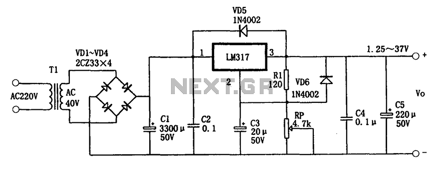
The adjustable power supply circuitry operates within a voltage range of 1.25 to 37V. It utilizes a three-terminal regulator, which is known for its good performance and stability. The compact size of the design facilitates easy installation, and it...
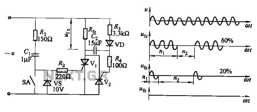
The output waveform of the thyristor zero trigger circuit is a sine wave, which does not generate electromagnetic interference like a phase-shift trigger circuit. This circuit serves as a basic thyristor power adjustment mechanism. In the circuit diagram, the...
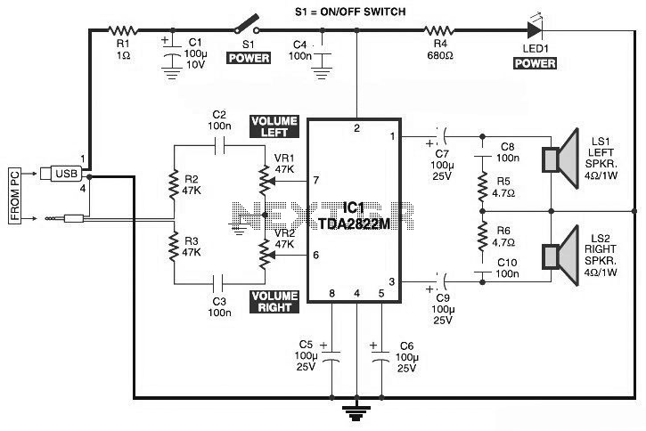
This is the circuit diagram of a USB-powered computer speaker, commonly known as multimedia speakers for PCs. The circuit features a single-chip design, operates on a low-voltage power supply, and is compatible with USB power from a computer. The USB-powered...
This preamplifier is a requirement resulting from many friends to provide a high-quality preamplifier, capable of driving high-quality power amplifiers with good sound. It is not, however, difficult to make; it combines simplicity and handiness. It does not allocate...
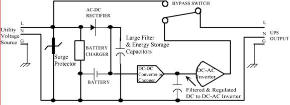
Thomas Edison developed the incandescent light bulb, which operated from a 110-volt DC source. The primary drawback of DC power was that it could only be distributed over short distances without needing to be regenerated. In the early 1900s,...
Warning: include(partials/cookie-banner.php): Failed to open stream: Permission denied in /var/www/html/nextgr/view-circuit.php on line 713
Warning: include(): Failed opening 'partials/cookie-banner.php' for inclusion (include_path='.:/usr/share/php') in /var/www/html/nextgr/view-circuit.php on line 713