
Processor Fan Control
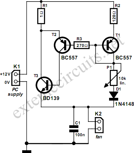
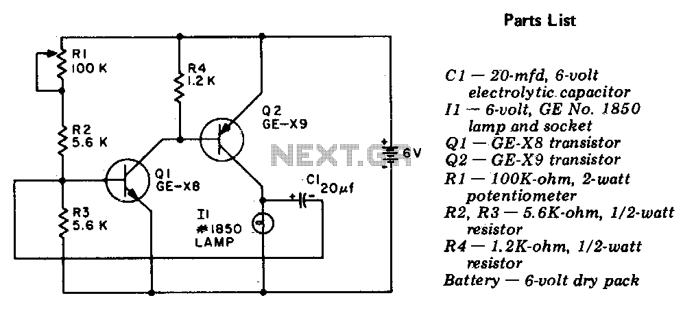
The circuit operates primarily by regulating the voltage supplied to the fan, thereby controlling its speed and the associated noise level. The transistors T1 and T2 function as switches that are triggered by the varying voltage levels determined by the potentiometers P1 and P2. As the resistance of P1 is adjusted, it alters the base current supplied to T1 and T2, which in turn modulates the fan's operation.
Resistor R1 serves a critical role in ensuring that a stable current flows through the circuit, contributing to the reliable operation of the transistors. The relationship between R1 and R2 is crucial; the design ensures that R1's current is significantly higher, allowing for the necessary amplification to drive the fan effectively. R3 acts as a safeguard, limiting the base current to T2 and preventing it from exceeding safe operating levels, which could potentially damage the transistor.
Diode D1 is essential for maintaining the correct voltage at the base-emitter junction of transistor T3, even when the resistance of P2 is minimized. This feature ensures that T3 can continue to operate effectively, allowing for consistent fan speed control. The overall simplicity of this circuit, combined with the use of readily available components, makes it an excellent solution for reducing fan noise in older PC models. The design can be easily adapted or modified to suit specific requirements or preferences, enhancing its utility in various applications.Fans in PCs can be objectionably loud. In many cases, the amount of noise produced by the fan can be considerably reduced by lowering its speed. Although this will decrease the amount of cooling, this need not be a problem as long as you don`t go overboard with slowing down the fan.
Particularly with older-model processors, which consume quite a b it less power than the latest models, this trick can be used without any problems. This circuit is anyhow intended to be used with relatively old PCs, since more recent models generally have a fan control circuit already integrated into the motherboard. These controllers ensure that the amount of cooling is increased if the processor becomes too warm and decreased if the processor temperature is relatively low.
The circuit described here consists of only a handful of components, which you will probably already have in a drawer some-where. Transistors T1 and T2 are driven into conduction by the base current‚owing to the fan via P1 and D1. There will always be a current‚owing through R1, and it will be approximately 120 times as large as the current through R2.
R3 has been added to prevent the base current of T2 from becoming too large when P2 is set to its minimum resistance. D1 ensures that even at this extreme setting, the voltage on the base-emitter junction of T3 will still be large enough to allow it to conduct.
🔗 External reference
Related Circuits
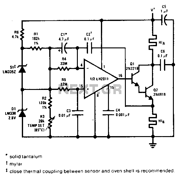
This proportional control crystal oven heater utilizes lead/lag compensation to achieve rapid setting. The time constant can be adjusted using resistor R4 and the compensating resistor R5. It is advisable to use a regulated supply for Q2 if it...
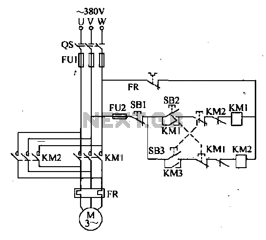
The forward and reverse dual interlock control circuit is based on the control circuit depicted in Figure 4-4, with an enhancement that incorporates a composite mechanical button interlock. The advantage of this circuit is that it allows the motor...
There are many variations in definitions of what exactly constitutes a robot. Consequently, it can be challenging to compare the number of robots across different countries. To provide a universally acceptable definition, the International Organization for Standardization (ISO) defines...
The circuit is capable of enhancing the system power factor to a value exceeding 0.99. It effectively reduces the waveform distortion of the input supply current, ensuring compliance with GB15144 standards, with a distortion index lower than level L....
TV video signal processor circuit. The ECG1064 chip includes a primary video amplifier, two sync pulse amplifiers, a look-out protector, a noise detector, two noise gates, an automatic gain control (AGC) detector, an intermediate frequency (IF) AGC amplifier, a...
The circuit is a two-stage, direct-coupled transistor amplifier configured as a free-running multivibrator. Both the flash duration and flash interval can be adjusted by turning the potentiometer, R1. The described circuit operates as a two-stage, direct-coupled transistor amplifier, functioning as...