
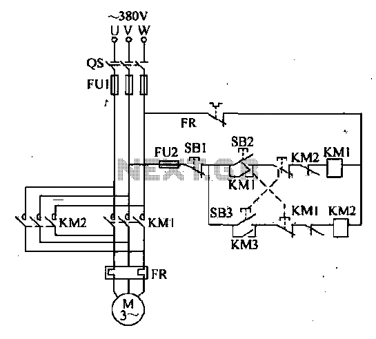
Double interlocking three-phase asynchronous motor control circuit
The forward and reverse dual interlock control circuit is designed to enhance the operational safety and reliability of motor control systems. The circuit employs a combination of mechanical and electrical interlocks to prevent simultaneous activation of forward and reverse operations, which could otherwise lead to equipment damage or hazardous conditions.
In this circuit, two start buttons, SB3 and SB4, are utilized for forward and reverse motor operations, respectively. The mechanical interlock ensures that pressing one button will physically prevent the other from being engaged, thereby enforcing a clear operational protocol. The electrical interlock further reinforces this by using relay contacts that disengage the opposite start button when one is activated.
The circuit typically includes a power source connected to the motor through a relay system. When the user presses the forward start button (SB3), the relay engages, allowing current to flow to the motor in the forward direction. Simultaneously, the mechanical interlock prevents the reverse button (SB4) from being pressed. If the user wishes to change the direction of the motor, they can simply press the reverse button (SB4) without needing to first stop the motor with SB1. The electrical interlock ensures that the motor is safely stopped before reversing direction, thus preventing any potential damage.
In addition to the interlock features, the circuit can be designed to include indicator lights that signal the current operational status of the motor (forward, reverse, or stopped). This provides visual feedback to the operator, enhancing safety and operational awareness.
Overall, the forward and reverse dual interlock control circuit is a sophisticated solution for controlling motor operations, emphasizing safety, reliability, and user convenience in various industrial and commercial applications.Shown in forward and reverse dual interlock control circuit, on the basis of the control circuit in Figure 4-4 on the increase in the composite mechanical buttons mutual lock link. The advantage of this circuit is: If you want to run the motor forward reverse, do not press the stop button SB1, as long as the direct anti-press to turn the start button SB3; of course, from forward to reverse operation, as well. This circuit has a dual electrical and mechanical interlock, not only to improve the reliability of control, and can achieve a reverse forward a stop a stop control, but also to achieve a forward reverse a stop control.
Related Circuits
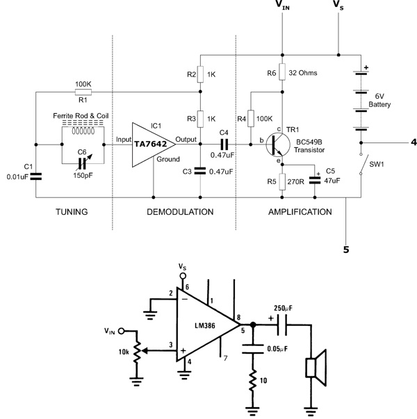
This functioning radio was built for an electronics module. The specified design was modified to include batteries, a switch, and a speaker instead of headphones. An additional amplifier circuit was required to power the speaker driver. Although not necessary,...
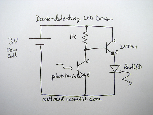
The following circuit illustrates a simple and inexpensive dark-detecting LED circuit. Features include the use of photoresistors, specifically a photocell or LDR, and an LED. This circuit utilizes a light-dependent resistor (LDR) as the primary sensing element. The LDR exhibits...
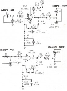
Preamplifiers are utilized to amplify low-level signals, such as those from microphones and tape heads, before they are sent to power amplifiers. Power amplifiers typically exhibit lower sensitivity. The frequency response can also be adjusted and optimized at the...
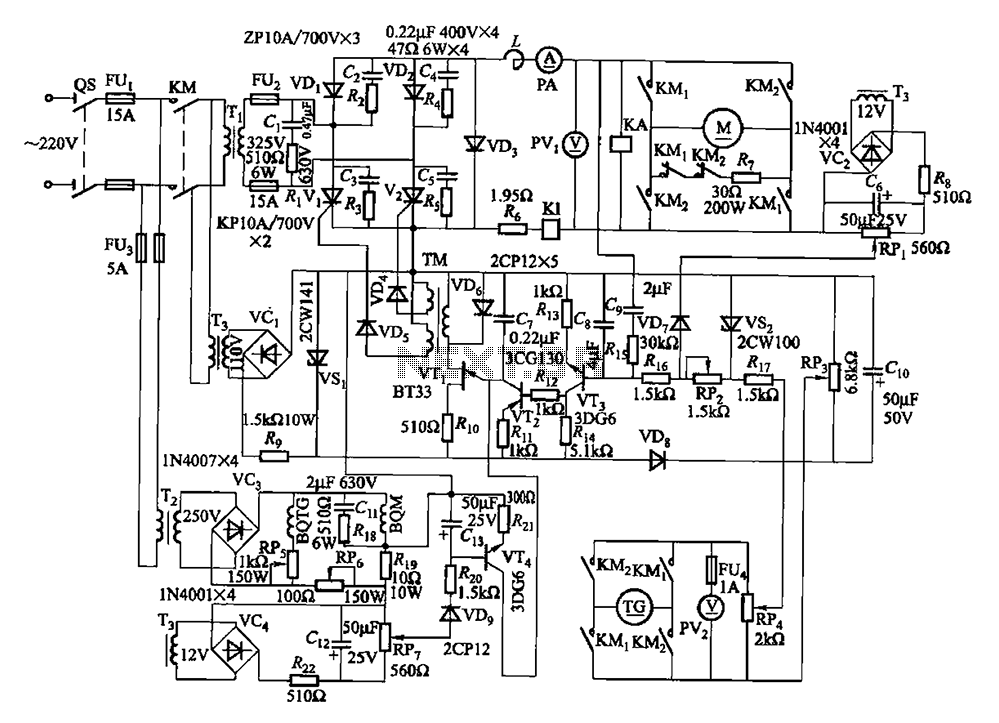
The circuit encompasses a main circuit, a trigger circuit, speed negative feedback, negative feedback differential voltage, a current cut-off circuit, loss of field protection, and other components. Given that the motor power is small (1.1 kW), a single-phase circuit...
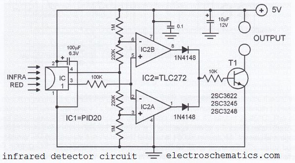
This infrared detector circuit utilizes a passive infrared detector component, PID20, which converts heat radiation into electrical impulses. The output voltage of the PID20 increases when an object approaches, provided that the object is warmer than the surrounding environment....

This circuit exhibits an exceptionally fast high-frequency response, as demonstrated by applying a 100 kHz square wave to the input. All graphs were produced using Tina Pro. The circuit's design is optimized for high-frequency applications, showcasing rapid response times that...