
Production of automatic re-set timer for crime prevention buzzer that uses PIC
The circuit design employs a simple yet effective approach to crime prevention. The integration of the PIC microcontroller allows for greater flexibility and precision in timing operations compared to the original timer. The use of transistors for relay control ensures that the device can handle the necessary current for the buzzer without excessive power consumption. Additionally, the inclusion of capacitors for noise filtering and voltage stabilization enhances the reliability of the circuit, making it suitable for long-term use in various environments. The careful consideration of component values, such as resistor and capacitor ratings, contributes to the overall functionality and durability of the crime prevention bell device. This design exemplifies a practical application of electronic components in security systems, showcasing how advancements in technology can improve existing solutions.The crime prevention bell device that I produced about 20 years ago works still in the active service. It worked many times to make the thief not operate well and not go into it. The bell keeps ringing generally though the bell rings as for the crime prevention buzzer when the thief was about to enter.
With this, after the fixed time, it is stoppe d because surroundings are troubled you and it is inconvenient. In addition, to operate even by degrees how many after it stops, the crime prevention buzzer is set again. However, because the timer had not been found to be suitable at the production this time, multi range timer ATC12112 of National was adjusted to five minutes of the turning on mode and it used it.
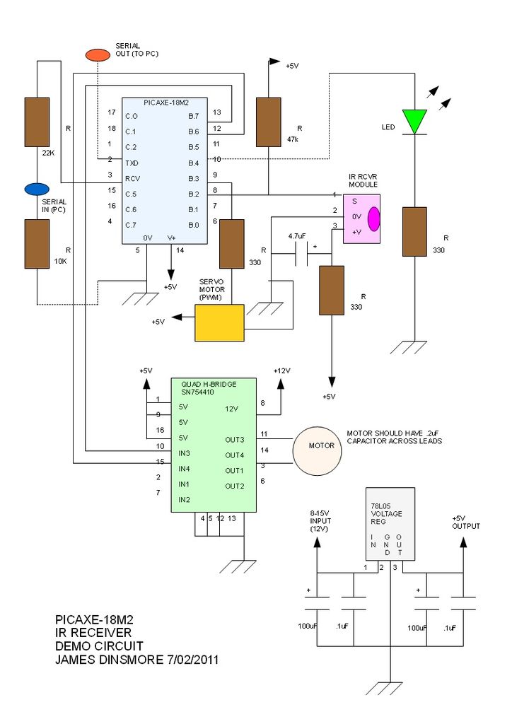
Recently Because it had come to be able to use the PIC microcomputer, the timer of this ATC12112 was replaced with PIC12F629. It introduces it because it easily made it to good. The schematic diagram displays only an alternative part of multi range timer ATC12112 of National. Please see the page of the design and the production of the crime prevention bell device about the entire circuit.
The seventh terminals (similar below the terminal number ATC12112) are connected with the power supply of +12V with the schematic diagram above. The eighth terminals are connected with the power supply side of the relay for the crime prevention buzzer.
The first terminal is connected with the power supply side of +12V of the warning bell. The relay for the crime prevention buzzer is turned off if the thief enters and warning rings, the 1st 12V hangs in the terminal, the voltage of about 5V hangs in PIC12F629 in the constant voltage circuit of R1 and D1, and PIC starts. The pin is the fourth input terminal of PIC for the switch of the time of the timer. It is three seconds in L of five minutes in H. It is for the test for three seconds. When the time of the timer passes, the fifth output of the pin of PIC becomes H from L. Therefore, Q2 and Q1 are turned on. And, it starts multiplying +12V from the terminal to the 8th relay for the crime prevention buzzer again and the relay being turned on.
The relay is turned on if all doors are closed at this time and the crime prevention buzzer is set again. 1000 F of C3 grips the key whether this operation goes well. The power supply of PIC has operated during the moment in the power supply only from the capacitor of C3 because 12 firstV of the terminal is 0V when it starts turning on the relay for the crime prevention buzzer in a word.
If hfe is 100 because the collector current of Q2 is about 2. 5mA, the current of the base is turned on by about about 25 A though there may not be 10k © of R5 by you because a recent transistor is efficient. If reliability is valued, you will put it. Please install the fourth capacitors C1 of PIC12F629 in pin (GP3). It malfunctions easily because of the noise such as feeling after the terminal directly by the hand if the capacitor is not installed in the input terminal of PIC.
The pin is not good at the fourth internal pull-ups of PIC in the input terminal (It is not possible to set it to the output). When it is a pull-up, an external pull-up resistor is needed without fail. The fourth pins become in the timer for five minutes in H and it becomes a timer by L for three seconds about PIC.
This doesn`t care about any voltage when operating only by checking it when starting. The temporal precision becomes the accuracy of the internal clock of PIC. Because it was an error margin of three seconds, the plus will become the error margin of about 1% in five minutes in the thing that I produced. I think it is quite unquestionable in this extent in this timer. 🔗 External reference
Related Circuits
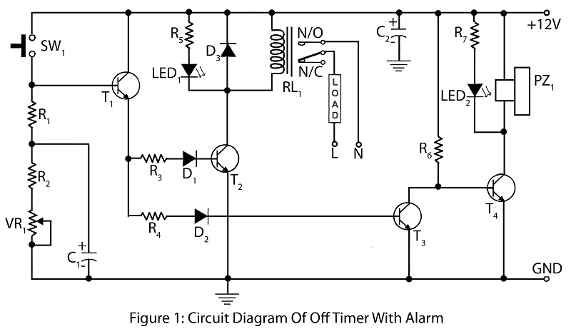
An off timer with an alarm is a straightforward project designed to indicate the end of a specified time period. The circuit utilizes four transistors. It includes a circuit diagram along with a parts list and a description of...
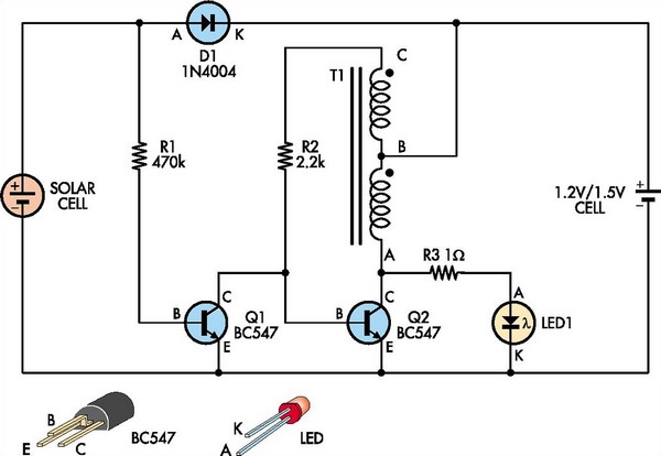
This white LED driver circuit is suitable for garden lighting applications. It automatically activates the LED at night and operates from a single 1.2V NiCad cell, which is recharged by a solar cell during the day. The prototype utilized...
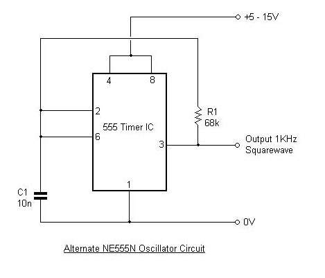
This article outlines the design and applications of the NE555 timer. The content is straightforward and informative, providing valuable insights into various components associated with the NE555. Readers can find and purchase these components through the article. It discusses...
The PICAXE basic code is straightforward: the main loop continuously checks for a signal from the IR receiver using the irin command. When a code is received, it is stored in... The PICAXE microcontroller is designed for simplicity and ease...

When an alarm or notification is needed after ten minutes, the circuit illustrated below can be utilized. This circuit is essentially a monostable multivibrator based on the IC NE555. When the reset push button is pressed, the green LED...
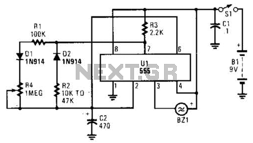
This timer circuit utilizes a 555 IC timer in conjunction with three 74LS193 counters to control an LED display. The circuit is activated by one individual who turns on the piezo buzzer BZ1 through Q1, simultaneously starting the timer....